Download
1 / 40
400 likes | 451 Vues
Understand loss types in YBCO coated conductors for utility power. Explore external field, transport, and combined losses, with special considerations for transport loss AC only. Discover implications for transmission lines, transformers, fault current limiters, and motor/generator applications.

E N D
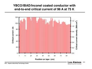
AC Loss For YBCO Coated Conductor In Utility Power Applications Department of Materials Science and Engineering M. Sumption, Milan Majorosand E.W. Collings 1LASM, MSE, Ohio State University Sixth Annual EPRI Superconductivity Conference and Task Force Meeting (Sep'06) Acknowledgements: V. Selvamanickam (S-power), Funded by AFSOR Phase II (LEI) and previous Phase I (HTR).Also, Summer Research Faculty, ARFL
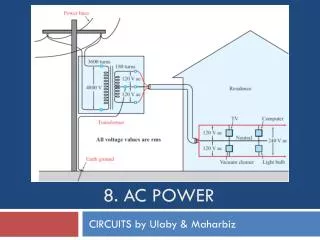
Representative Applications 1. Transmission Line 2. Transformer 3. Fault Current Limiter 4. Motor/Generator
Loss Types in YBCO Transport Loss External Field Loss Combined Transport and Field Loss Transmission Configuration Special Considerations for YBCO
Transport Loss AC Current only (No Field) Hysteretic Losses (mostly), eddy current loss PI/Ic4 for strip, also P w2 Filamentarization + twist does not help Filamentarization + Braid works
Department of Materials Science and Engineering External Field Loss Loss 500 Hz/ 1 T 1 kW/m 70 mW/m 20 W/m Hysteretic Ferromagnetic Substrate Normal Metal Eddy Currents Coupling Eddy Currents Cu I2R loss = some W/cm3
Combined Transport and Field Loss IDC + BAC IAC + BDC IAC + BAC Relative Phase Relative Size
Transmission Lines -- I Approximate as thin-wall, hollow tube Losses go down as h (SC thickness) Losses go up with I3, down as R2 Current into page Implication – (1) YBCO Q < BSCCO Q (2) I/Ic fraction again important, striping, cutting, not needed to first order.
Transmission Lines II -- GAPS Losses << transport Q of isolated tapes, Q width B BUT, gaps let field through, so More SC exposed to B and thus Q increases Q gap2 in end regions Make Gaps small, route field to keep it out
Special Considerations for YBCO Influence of high Aspect Ratio Influence of ferromagnetic (Even “soft” ferromagnetic elements) Transposition Stability Protection
Representative Applications 1. Transmission Line 2. Transformer 3. Fault Current Limiter 4. Motor/Generator T- Line Configuration Stray External Field Dominated Resistive – Transport, inductive external field Rotor – DC + Negligible ripple unless shielding removed
Transformer Loss small where B thin side Loss large when B Bstray – 0.1-0.2 T B main – 1-2 T Can either reduce width or stripe – but striping requires transposition
Department of Materials Science and Engineering Externally Applied Field Loss at OSU–4 cm Sample Solenoid Rig Primary coil: at least 200 Hz at 140 mT, built for 500 Hz Pick-up Compensation
(2) Racetrack Primary – 20 cm samples active field Applied Fields of 100 mT, 2% field homogeneity
Department of Materials Science and Engineering Power Loss for Unstriped and 40 Stripe Conductors striping
Transposition Can either twist Or transpose using small resistive links
Fault Current Limiter Two types • Resistive –Transport loss only • Inductive – saturated or non-saturated Fe – back to the case of the transformer
Transport and Helmholtz Rig AC Current only (No Field) Hysteretic Losses (mostly), eddy current loss PI/Ic4 for strip, also P w2 Filamentarization + twist does not help Filamentarization + Braid works
Department of Materials Science and Engineering YBCO Coated Conductor Transport Loss • More or less follows Norris cubic equation (ellipse) • But why ellipse • Not perfect agreement • Reasons • Substrate ferromagnetism • Non-uniform Jc
Field Enhancement due to Ferromagnetic layer Tape width = 5 mm YBCO film thickness = 1 m Buffer layer thickness = 0, Substrate thickness = 100 m, YBCO film Jc=1010 A/m2
Motor/Generator Rotor DC element with AC ripple only Stator High External Field in Regions (1-2 T) Combined with transport current
Department of Materials Science and Engineering Section III: Coil Data and Dynamic R
Department of Materials Science and Engineering Dynamic Resistance: Full Penetration Interactions of DC current and AC field in superconductors leads to a loss. Energy for “Alternating Field Loss” is provided by the magnet Energy for this latter loss is provided by the DC power Supply, and is interpreted as a resistance This is the dynamic resistance, and is given by the equation at right This model is valid for Full Penetration
Department of Materials Science and Engineering Dynamic Resistance: Partial Penetration (Heuristic) SI unit Let the penetration along the width be x Let the critical penetration be x* = w-a Where a is the region of loss-less current flow at the sample interior Clearlya = (I/Ic)w leading to K 1 Using Bm=K0Jcx*, we can find that A criterion for Ic reduction based on Hm
Department of Materials Science and Engineering Dynamic Resistance in Coils If Note: This is DC current and AC field, but AC current and DC field has similar properties, also AC current and field
Looking More Closely at Dynamic Resistance Onset This leads to 1/(JcwK) = 50 Which means that if K 1 and w = is 2m. But this should be no surprise, since really, the thickness is controlling the penetration Slope = -50 This leads to a good fit for the experiment to the theory, but now
Department of Materials Science and Engineering Looking More Closely at Dynamic Resistance Imperfect extrapolation Can be usefully re-written Thus
Department of Materials Science and Engineering Operative Equations This denotes the onset of dynamic resistance. In our case the resistance is large, and this becomes a kind of Ic,eff The resistance value itself scales with dB/dt and w Even as w becomes reduced and the onset of dynamic resistance no longer imitates a SC transition, we will have significant losses from this component, given at left If w = 1 cm, I = 200 A, and Iop = 07Ic, P/L = 0.12 Watts *dB/dt
Department of Materials Science and Engineering Loss Numbers for Dynamic Resistance Dynamic Resistance only calculated for unstriped
Department of Materials Science and Engineering Machines and Design for Application 1. What about stability and protection? 2. What are dominant losses in various applications and what kind of conductor are needed for each application? 3. What will the likely operating parameters of the machine be, how is that related to YBCO characteristics
Department of Materials Science and Engineering Rotor Fields Rotor scalar fields at right in T
Department of Materials Science and Engineering Some Targets and Estimates for Motor/Generator Barnes, Sumption, Rhodes, Cryogenics 45 (2005) 670–686 No estimates here of Dynamic resistance effects
Department of Materials Science and Engineering Adding in Dynamic Resistance Effects If w = 1 cm, I = 200 A, and Iop = 07Ic, P/L = 0.12 Watts *dB/dt Jim Parker [LEI] estimates that unshielded rotors will have a “field” somewhere in the 2 mT range [40 mT peak at worst spots] • Shielded rotors should have this attenuated by a factor of 1000 [J Parker] • dB/dt = 4Bmf = 4*2 x 10-6 * 500 = 10-3 T/s – for unstriped conductor this leads to 0.1 mW/m for shielded rotor, but much larger for all-cryogenic machine (unshielded rotor) – 100 mW/m. Striping will correct this sufficiently • For stators, field is 106 times larger, so filaments 104 times smaller than 1 cm at required at minimum – consistent with constraints from hysteretic loss
Adding Up Losses in a Generator SC rotor: 0-2 WRotor shield: 360 WWindage in a cryogenic liquid or gas machine: 1500 WStator, Cu based: 2000 W Machine scenarios • Conventional • Hybrid (Cryogenic rotor, oil cooled stator) • All Cryogenic, liquid cryogen • All Cryogenic, Conduction
Variants 0. Conventional: Benchmark. All the variants below are assumed to have the target of a greater energy density (as compared to this option) their main goal. Losses are 1500 W + 2000 W + 360 W + normal stator Watts = nearly = 3860 - 4000 W. 1. Hybrid, SC rotor and Cu stator, the latter oil cooled at RT. Increases powder density, avoids difficulty of stator windings. Losses are = 1500 W + 2000 W + 360 W + [0-2 W * 10] = nearly = 3860 - 4000 W. No real lessening of losses, but increased rotor field, thus machine power, thus power
Variants II 2. All SC, operating in liquid cryogen--Losses are unessential, since all in hydrogen ] = [1500 W + 2000 W + 360 W + 0-2 ]*[factor related to inconvenience of hydrogen liquification] = nearly = 4000 W * [very small number] = not important practically, but would be same for Cu system, so must win on power density 3. All SC, operating in a cryocooled state.Losses are = [no windage (assume operate in vacuum) + 2 W (assume non-metallic stator support and low loss stator conductor) + X W from stator ] * [factor of 10 penalty factor] = nearly = stator losses * penalty factor ----But this implies operation in vacuum, ac tolerant SC
Integrating the Conductor Into the Machine Investigations of Winding Geometries I-V loss Measurements for various diamond stator windings
Ag YBCO Buffer Substrate groove depth extends into substrate Department of Materials Science and Engineering Low Loss Conductors: Will They be “Stable” Enough for Machines? Striped YBCO Layer, striped overlayer, resistive substrate Can we afford not to stripe Cu overlayer from a stability-protection/current sharing? Can we afford the loss if we don’t?
Department of Materials Science and Engineering Stability/Protection/Current Sharing vs AC loss Perhaps we can stripe with little or no connection (Some will not agree) We must remember that YBCO at relevant operation regimes are arguably nearly intrinsically stable (energy margin), but they are very difficult to protect. But this is not directly helped by filament interconnection Current sharing would reduce possible current distribution inhomogeneity – or Ic inhomogeniety This can be perhaps addressed with connections that are very high resistance – 400 cm or more
Summary 1. Transmission Line 2. Transformer 3. Fault Current Limiter 4. Motor/Generator T- Line Configuration Stray External Field Dominated Resistive – Transport, inductive external field Rotor – DC + Negligible ripple unless shielding removed