Download
1 / 63
630 likes | 759 Vues
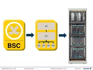
Introduction to ZXC10-BSC. Content. A BSC overview B subsystems of BSC. A BSC Overview. Position in system Hardware Architecture Mechanical and electrical Features Logical Structure Performance Working environment. Position in system. BSS. MS. BSC. BTS. VLR. BTS.

E N D
Content A BSC overview B subsystems of BSC
A BSC Overview • Position in system • Hardware Architecture • Mechanical and electrical Features • Logical Structure • Performance • Working environment
Positionin system BSS MS BSC BTS VLR BTS BTS MS HLR MSC PSTN MS ISDN BTS BSC BTS BTS MS A Interface Um Interface Abis Interface other MSC
HIRS: High-speed Interconnect Router Subsystem CDSUS:Channel/Data Service Unit Subsystem SVBS: Selector & Vocoder Bank Subsystem TS: Timing Subsystem CPS: Call Processing Subsystem BSM: Base Station Management Subsystem TO MSC/LE BSM Hardware Architecture TS SVBS 。 。 。 HIRS SVBS TO CDSUS CPS BTS
Mechanical and electrical Features • BSC consists of central rack and vocoder rack. • Central rack and vocoder rack apply standard rack and insertion box. The different types of insertion box are composed of different inserted boards. • From top to bottom, the whole rack contains: a power distribution insertion box, 3~5 function insertion boxes, a fan box and anti-dirt frame. • There are three kinds of function insertion boxes: HIRS layer: consists of PSMB, NIM, NCM, etc. CDSU layer: consists of PSMB, CDSU(or CDSU, CPM, TCM, GPSTM), etc. SVBS layer: consists of PSMB, SVM, SVICM, etc. Max.number of cards in each function insertion box:22
¬ System BSC ¬ Subsystem CDSUS SVBS TS CPS BSM HIRS CPM ¬ Module NIM SVM TCM BSC _CDSU NCM SVICM GPSTM SVE SVP ¬ Unit Logical Structure
Performance • Max. number of E1links of A interface: 240(240 x 30 =7200 circuits) • Max. number of selector/vocoder :7200 • Max. traffic processing capability:5040 Erl (7200 x 0.7) • BHCA:310K • Max number of subscribers:170K(0.03 Erl per subscriber,5040/0.03) • Max number of BTS can be connected to BSC : • 380(single carrier frequency and omni-direction, 192channels/BTS, 13.2erl,5040/13.2 ) • 128 (single carrier frequency with three sectors,192channels/BTS , 60 traffic channel, 39.6erl,5040/39.6) • Access Network Interfaces Interoperability Specification : IOS2.x,IOS3.x,IOS4.x • Support soft handoff between BSC • 8K、13K QCELP and 8k EVRC vocoder • Data service:9.6kbps、14.4kbps
Working environment • Long term working temperature: +15℃~+35℃ • Short term working temperature: 0℃~+45℃ • Long term working humidity: 40%~65% • Short term working humidity: 15%~90% • The concentration of dirt with diameter larger than 5μm should be ≤3×10⁴grains/m. In addition, the dirt should not be conductive, electro-magnetic or corrosive.
B Subsystems of BSC • HIRS: High-speed Interconnect Router Subsystem • CDSUS:Channel Data Service Unit Subsystem • SVBS: Selector/Vocoder Bank Subsystem • TS: Timing Subsystem • CPS: Call Processing Subsystem
B Subsystems of BSC • HIRS: High-speed Interconnect Router Subsystem • CDSUS: Channel Data Service Unit Subsystem • SVBS: Selector/Vocoder Bank Subsystem • TS: Timing Subsystem • CPS: Call Processing Subsystem
HIRS HIRS Subsystem is switching center and packet data exchange platform of BSS。 Function ofHIRS: • Packet data switching • Flow control • Timing distribution,monitor GPS • Software downloading
TS BSC_CDSU BSC_CDSU SVBS SVBS Structure of HIRS Ethernet Interface HIRS clk TOD clk BSM dis dis U gateway co U gateway co 2 2 I C I C NCM NCM NCM NCM NIM NIM NIM NIM CPS 422 CPM 0 CPM 0 7 7 0 7 7 CDSUS non-channelized E1 non-channelized E1 BDS BDS BTS_CDSU BTS_CDSU BDS BTS_CDSU
NCM —— Network Control Module • Manage the HIRS • Interface to Base Station Management Subsystem(OMC) • Timing receiving and distributing
Functions of various parts • U-gateway unit: Implements dual-bus arbitration and routing the interior or outgoing packet. • ATM interface unit: Implements interconnection to another frame, and provides interfaces for future expansion. • Main control unit: The CPU system, which implements distributing various modules’ software and configuration information; modifying, notifying and confirming local device status; maintaining local copy of the configuration database; detecting, isolating, reporting and recovering the HIRS network errors; monitoring the performance of HIRS network; receiving broadcast TOD message, controlling and maintaining GPSR (GPS receiver). Also it implements operation and maintenance of the whole BSS system. • Clock power supply reset unit: Provides the power supply to the board, and 1.5V power supply to the backplane; clock driving and distributing; provide board reset signal. • Main control logic unit: Implements active/standby competition and switchover, in-board status detection, control and reporting.
NCM Panel • HL12: Running indicator (green), with the blinking speed representing different processes running; • HL14: Alarm indicator (red), lighting up when a software error occurs; • HL2: Active indicator (green), lighting up when the board is in active state; • SW5: Manual active/standby switchover button; • SW3: Reset button.
NIM -Network Interface Module • Receive/send RS-422 serial data • Receive/send data through DISCO • 8+1 redundancy • Clock receiving and distributing
Functions of various parts • Control unit: Implements board startup, self-test, status error reporting, N+1 switchover etc. • DISCO Unit: Transmits the data in the reception buffer to the UGATE of the NCM, or saves the data from the UGATE into the sending buffer. • HDLC Unit: Receives the HDLC data frames from the CPM, NCM, SVICM or CDSU and save them into the buffer, or takes data from the sending buffer, converts them into the HDLC format and sends them to the CPM, NCM, SVICM or CDSU. • 422 driver: Drives the HDLC data code flow, PP2S and CHIP signals. • GTLP driver: Drives the DISCO dual-bus data and control signals.
NIM RUN ALM ACT RST NIM Panel • RUN: A green indicator, blinking when the board works normally. • ALM: A red indicator, blinking or lighting up in case of board failure. • ACT: A green indicator, lighting up when the board is in master mode. • RST: Reset button.
Subsystem of BSC • HIRS: High-speed Interconnect Router Subsystem • CDSUS: Channel Data Service Unit Subsystem • SVBS: Selector/Vocoder Bank Subsystem • TS: Timing Subsystem • CPS: Call Processing Subsystem
CDSU Subsystem • Convert signal between RS-422 interface and non-channelized E1,transfer signaling and traffic data between BSC and BTS. • BSC-CDSU and BTS-CDSU,and have the same hardware structure.
BSC-CDSU-Channel/Data Service Unit IN BSC E1 Interface Unit Route Arbitra tion Unit E1 Interface RS422 Interface Unit E1 Interface • Provide the E1 link interconnection with BTS-CDSU; • Support flow control; • Supply the RS-422 interface interconnect with NIM; • Monitor and maintain E1 link; • Routing and BUS arbitration。 Control Unit BSC-CDSU
BTS-CDSU-Channel/Data Service Unit IN BTS RS422 Interface Unit Route Arbiter Unit E1 Interface E1 Interface • Provide the E1 link interconnect with BSC-CDSU ; • Support daisy-chain between BTS and provide the E1 link; • Provide RS-422 interface interconnect with CCM。 • Monitor and maintain E1 link; • Flow control • Routing and BUS arbitration Control Unit BTS-CDSU
CDSU Panel RUN • RUN Running • ALARM Alarm • SYNCA Synchronization A • SYNCB Synchronization B • RST Reset Button ALM SYNCA SYNCB RST
Subsystem of BSC • HIRS: High-speed Interconnect Router Subsystem • CDSUS:Channel Data Service Unit Subsystem • SVBS:Selector/Vocoder Bank Subsystem • TS: Timing Subsystem • CPS: Call Processing Subsystem
SVBS SVBS is the physical unit of Selector/Vocoder resource pool in BSC,composed of 1 SVICM and 8 SVMs. • Path selection:select a path in several soft handoff path by the quality • Transcoding:convert code between PCM and QCELP or EVRC • Echo cancellation: Echo cancellation in forward link • Judge and implement soft handoff • Power control • Signaling handling(No.7 and/or v5.2)
SVICM - Selector & Vocoder Interface Control Module • S-HIRS • Distribute forward traffic and signaling(SVMSVICM NIM) • Distribute reverse traffic and signaling (SVMSVICM NIM) • Distribute signaling within SVBS(SVMSVICM ) • Receive and Distribute Clock and TOD message • Manage and control SVM • Interconnect with MSC(LE)
Functions of various parts • SVC unit: The kernel control part of the SVICM. With a high-performance processor as its CPU, it is responsible for the maintenance and management of the SVBS internal software and configuration data and the control and maintenance of various SVMs in the SVBS; • DISCO logic unit: Implements communication with the HIRS network, that is, link with the HIRS network of the BSC through a gateway; • Gateway Unit: Implements the communication with the SVM; • Digital Trunk Interface(DTI) unit: Implements the PCM link between the MSC and the BSS; • Clock generation unit: Generates the working clock (20ms) required by the SVBS with the received system clock as reference.
RUN ALM SYNA SYNB SYNC SYND RST SVICM Panel • RUN: Running indicator (green), blinking during operation; • ALARM: Alarm indicator (red), lighting up when a software error occurs; • SYNA: 1st E1 connection indicator, lighting up to indicate that the E1 link is connects; • SYNB: 2nd E1 connection indicator, lighting up to indicate that the E1 link is connects; • SYNC: 3rd E1 connection indicator, lighting up to indicate that the E1 link is connects; • SYND: 4th E1 connection indicator, lighting up to indicate that the E1 link is connects; • RST: Reset button.
SVM - Selector & Vocoder Module • transcoding between PCM and QCELP or EVRC • reverse outer-loop power control • soft handoff • handle layer 3 of Abis interface and layer 2 of IS-95 signaling • assign the timeslot
SVE1 SVP 数据接口 SVE2 维护总线 时钟接口 HW接口 SVE15 Function of SVM • selector/vocoder processor • selector/vocoder Element SVICM receive traffic data from the RS-422 port of NIM then forward to SVM,SVP forward to SVE,SVE transcoding to PCM and send through HW,in other direction,SVE transcoding PCM to QCELP or EVRC,then send to SVP,then to SVICM,and then NIM. A SVM contain 1 SVP and 15 SVEs.
Functions of various parts • Main control unit: Performs the control of SVE and data interface unit; implements selector and power control functions; fault detection and reporting; • Data interface unit: Provides a packet data interface for the communication within the BSS system; • HW interface unit: Implements PCM clock conversion and provides PCM code flow data channel for SVE; • SVE: Implements PCM-QCELP conversion, with 15 vocoders; • Clock, reset and power circuit: Implements clock and board reset of the main control unit, and provides all types of power supplies, including 5V, 3.3V and 2.5V.
SVM Panel • RUN: Running indicator (green), blinking during working normally; • ALARM: Alarm indicator (red), lighting up when a software error occurs; • RESET: Reset button.
Subsystem of BSC • HIRS: High-speed Interconnect Router Subsystem • CDSUS:Channel Data Service Unit Subsystem • SVBS: Selector/Vocoder Bank Subsystem • TS: Timing Subsystem • CPS: Call Processing Subsystem
Timing Subsystem According to the CDMA standard,BSC and BTS independently synchronize the timing signal provided by GPS Timing subsystem provide such timing signal: • PP2S • 16chips:19.6608MHz • TOD message
TCM Panel • RUN green Lights up when the TCM works normally • ALM red Lights up when the TCM works abnormally • LOCK green Lights up when the TCM is locked • CLK: an SMA socket, used for monitoring of the TCM’s 16chip timing signal • PP2S: an SMA socket, used for monitoring of the TCM’s PP2S timing signal and for BS testing
Subsystem of BSC • HIRS: High-speed Interconnect Router Subsystem • CDSUS:Channel Data Service Unit Subsystem • SVBS: Selector/Vocoder Bank Subsystem • TS:Timing Subsystem • CPS: Call Processing Subsystem