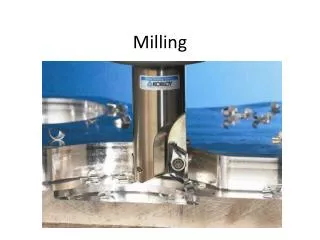
Milling Cutters
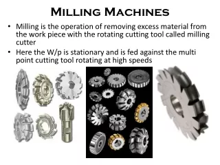
Milling Cutters. Session 12. Milling Cutter Materials. Cutter Characteristics Harder than metal being machined Strong enough to withstand cutting pressures Tough to resist shock resulting from contact Resist heat and abrasion of cutting Available in various sizes and shapes.

Milling Cutters
E N D
Presentation Transcript
Milling Cutters Session 12
Milling Cutter Materials • Cutter Characteristics • Harder than metal being machined • Strong enough to withstand cutting pressures • Tough to resist shock resulting from contact • Resist heat and abrasion of cutting • Available in various sizes and shapes
High-Speed Steel • Iron with additives • Carbon: hardening agent • Tungsten and Molybdenum: enable steel to retain hardness up to red heat • Chromium: increases toughness and wear resistance • Vanadium: increases tensile strength • Used for most solid milling cutters
Cemented-Carbide • Higher rates of production (3-10 times faster) • Must select proper type of carbide • Straight tungsten carbide: cast iron, plastics • Tantalum carbide: low/medium-carbon steel • Tungsten-titaniumcarbide: high-carbon steel
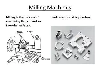
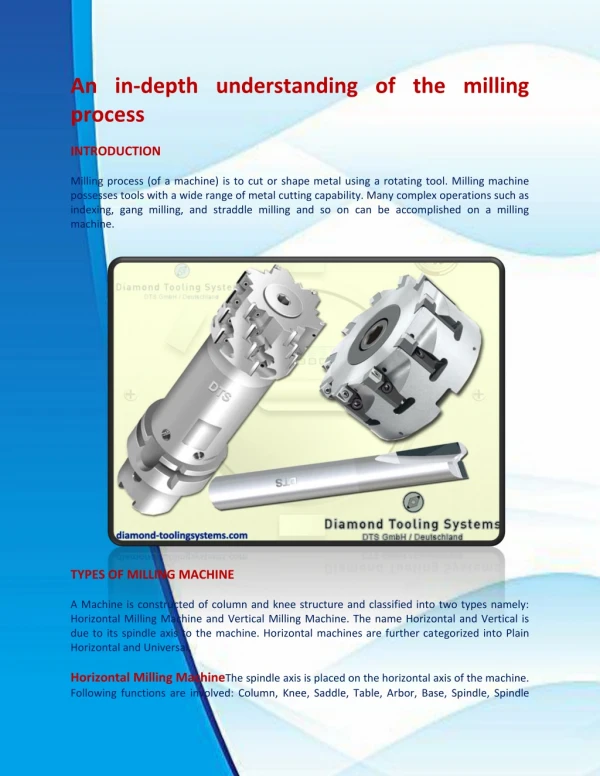
Plain Milling Cutters • Once widely used • Cylinder of high-speed steel with teeth cut on periphery • Used to produce flat surface • Several types • Light-duty • Light-duty helical • Heavy-duty • High-helix
Light-Duty Plain Milling Cutter • Less than ¾ in. wide, straight teeth • Used for light milling operations • Those over ¾ in have helix angle of 25º • Too many teeth to permit chip clearance
Heavy-Duty Plain Milling Cutters • Have fewer teeth than light-duty type • Provide for better chip clearance • Helix angle varies up to 45º • Produces smoother surface because of shearing action and reduced chatter • Less power required
High-Helix Plain Milling Cutters • Have helix angles from 45º to over 60º • Suited to milling of wide and intermittent surfaces on contour and profile milling • Sometimes shank-mountedwith pilot on end and usedfor milling elongated slots
Standard Shank-Type Helical Milling Cutters • Called arbor-type cutters • Used for • Milling forms from solid metal • Removing inner sections from solids • Inserted through previously drilled hole and supported at outer end with type A arbor support
Side Milling Cutters • Comparatively narrow cylindrical milling cutters with teeth on each side and on periphery • Used for cutting slots andfor face and straddle millingoperations • Free cutting action at highspeeds and feeds • Suited for milling deep, narrow slots
Half-Side Milling Cutters • Used when only one side of cutter required • Also make with interlocking faces so two cutter may be placed side by side for slot milling • Have considerable rake • Able to take heavy cuts
Face Milling Cutters • Generally over 6 in. in diameter • Have inserted teeth made of high-speed steel held in place by wedging device • Most cutting action occursat beveled corners andperiphery of cutter • Makes roughing and finishing cuts in one pass
Shell End Mills • Face milling cutters under 6 inch • Solid, multiple-toothcutters with teeth on face and periphery • Held on stub arbor • May be threaded or usekey in shank to drive cutter
Angular Cutters • Teeth neither parallel nor perpendicular to cutting axis • Used for milling angular surfaces • Grooves, serrations, chamfers and reamer teeth • Divided into two groups • Single-angle milling cutters • Double-angle milling cutters
Angular Cutters • Single-angle • Teeth on angular surface • May or may not have teeth on flat • 45º or 60º • Double-angle • Two intersecting angular surfaceswith cutting teeth on both • Equal angles on both side of line at right angle to axis
Formed Cutters • Incorporate exact shape of part to be produced • Useful for production of small parts • Each tooth identical in shape • Sharpened by grinding tooth face (may have positive, zero or negative rake) • Important to maintain original rake • Difficult to sharpen
Types of Formed Cutters Concave Convex Gear Tooth
Metal-Slitting Saws • Basically thin plain milling cutters with sides relieved or "dished" to prevent rubbing or binding when used • Widths from 1/32 to 3/16 in. • Operated at approximately 1/4 to 1/8 of feed per tooth used for other cutters • Not advisable to key saw to milling arbor • Backlash eliminator should be engaged
End Mills • Cutting teeth on end as well as periphery • Fitted to spindle by suitable adapter • Two types • Solid end mill: shank and cutter integral • Smaller with either straight or helical flutes • Two flute or four flute • Shell end mill: separate shank
T-Slot Cutter • Used to cut wide horizontal groove at bottom of T-slot • After narrow vertical groove machined with end mill or side milling cutter • Consists of small side milling cutter with teeth on both sides and integral shank for mounting
Dovetail Cutter • Similar to single-angle milling cutter with integral shank • Used to form sides of dovetail after tongue or groove machined • Obtained with 45º, 50º, 55º, or 60º angles
Woodruff Keyseat Cutter • Similar in design to plain and side milling cutters • Small (up to 2 in) solid shank, straight teeth • Large mounted on arbor with staggered teeth • Used for milling semicylindrical keyseats in shafts • Designated by number system
Woodruff Cutters Number System Right-hand two digits give nominal diameter in eighths of an inch, preceding digits givewidth of cutter in thirty-seconds of an inch Diameter 06 x 1/8 = 3/4 in. # 406 Width 4 x 1/32 = 1/8 in.
Flycutters • Single-pointed cutting tool with cutting end ground to desired shape • Mounted in specialadapter or arbor • Fine feed must be used • Used in experimentalwork instead of a specially shaped cutter