Download
1 / 16
160 likes | 359 Vues
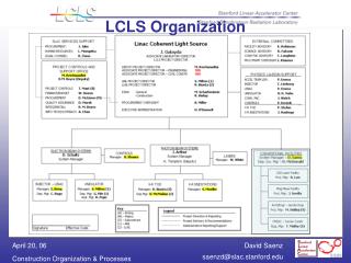
Introduction to the LCLS Undulators Heinz-Dieter Nuhn, SLAC / LCLS October 14, 2004. Undulator Overview Requirement Documents Undulator Fields and Tapering Cradle Components and Motion MMF Physics Requirements. Far Hall. Undulator. Near Hall. Linac Coherent Light Source.

E N D
Introduction to the LCLS UndulatorsHeinz-Dieter Nuhn, SLAC / LCLSOctober 14, 2004 • Undulator Overview • Requirement Documents • Undulator Fields and Tapering • Cradle Components and Motion • MMF Physics Requirements
Far Hall Undulator Near Hall Linac Coherent Light Source
Undulator Requirement Documents Index URL:http://www-ssrl.slac.stanford.edu/lcls/requirements.html
Summary of Nominal Undulator Parameters Undulator Type planar hybrid Magnet Material NdFeB Wiggle Plane horizontal Gap 6.8 mm Period Length 30.0± 0.05 mm Effective On-Axis Field 1.249 T Standard Effective K 3.49290 ± 0.015% Range of Effective Undulator Parameter K 3.5000 - 3.4929 (3.4804) Accumulated Segment Phase Error Tolerance 10 degrees(at any point along segment) Module Length 3.40 m Number of Modules 33 Undulator Magnet Length 112.2 m Standard Break Lengths 48.2 - 48.2 - 94.9 cm Nominal Total Device Length 130.954 m Quadrupole Magnet Technology EMQ Nominal Quadrupole Magnet Length 7 cm Integrated Quadrupole Gradient 3.0 T
Micro Tapering V: K values • The following list contains the nominal K values for the 33 undulator segments for the 6.8 mm gap height: To compensate energy loss from spontaneous radiation This amount of tapering requires only a negligible adjustment for break lengths. After achieving goal performance, tapering beyond saturation point is desirable. (up to 0.56% total)
Undulator Pole Canting Suggested by J. Pflueger, DESY • Canting comes from wedged spacers • 4.5 mrad cant angle • Gap can be adjusted by lateral displacement of wedges • 1 mm shift means 4.5 microns in gap, or 8.2 Gauss • Beff adjusted to desired value Source: Liz Moog
Canting the poles helps in many ways • Facilitates final setting of Beff • Remote control of position allows run-time adjustment • Allows compensating for temperature effect on field strength: ±1.0°C temperature error would require ±1.2 mm lateral shift of undulator Source Liz Moog
Effective B field vs. x See I. Vasserman’s Talk for Prototype Measurements Measured slope of 6.6 Gauss/mm agrees with calculations(~ 5.7 Gauss/mm for 3 mrad cant) Field variation allowance between segments is DB/B = 1.5x10⁻⁴, or DB = 2 Gauss, which translates to Dx = 0.3 mm ( or 1 micron in gap) Source Liz Moog
Using Undulator Roll-Away and K Adjustment Function Neutral; K=3.4965; Dx=+0.0 mm First; K=3.5000; Dx=-1.5 mm PowerTp; K=3.4804; Dx=+7.0 mm Last; K=3.4929; Dx=+1.5 mm RollAway; K=0.0000; Dx=+100 mm
Cradle Components • Cradle Components include • Undulator strongback arrangement mounted on horizontal slides • Vacuum chamber support • BPM • Quadrupole • WPM sensors • HLS sensors • (diagnostics chamber) • The undulator strongback arrangement (segment) is mountable on and removable from the cradle with the vacuum chamber in place and without compromising the alignment of the vacuum chamber. • Undulator strongback can be taken off the cradle for magnetic measurements • Complete cradle assembly will be aligned on Coordinate Measurement Machine (CMM).
Motions of the Cradle and of Cradle Components • Remotely Controlled Motion: • Cradle: x, y, roll • x, y motion of cradle ends are coupled • roll motion capability is to be used to keep roll constant • Undulator: x • Horizontal slide stages move undulator strongback independent of cradle and vacuum chamber • Manual Adjustment: • Cradle Movers to fixed support girder (AMP) • Quadrupole and BPM position to cradle.
MMF Physics Requirements • Earth Magnetic Field Compensation • Establish environmental magnet field in MMF to be equal to the environmental field at target location in undulator hall to better than 0.01 T. • MMF Temperature • Average ambient MMF temperature needs be 20.0 ± 0.1 oC to match the ambient undulator hall temperature of 20.0 ± 0.2 oC. • Magnetic Undulator Shimming to • Reduce phase error below 10 degrees at 0.15 nm. • Reduce 1st Field Integral below ±40×10-6 Tm • Reduce 2nd Field Integral below ±50×10-6 Tm2 • Definition of Standard Undulator Axis (SUSA) so that • SUSA is Parallel to Undulator Center Line • Effective K along SUSA is 3.4965 ± 0.0005 • Alignment of Quadrupole on Cradle with respect to CA*. • Tolerance: 40 mm (rms). • Routine Operational Checking of Undulator Segments • Remove 3 segments / month from undulator hall and replace with spares • Characterize magnetic field of removed segments and prepare for re-installation. See J. Welch’s and I Vasserman’s talks for details *Cradle Axis (CA) is identical to SUSA when undulator segment is in neutral horizontal position
Conclusions • Requirements and Specifications are available from the LCLS WEB site. • The main Physics Requirements Document (PRD) outlining the requirements for the undulator system is PRD1.4-001. The MMF specifications are found in PRD1.4-002. • Main Physics Task to be done at the MMF are • Undulator magnetic field tuning to specifications under same surrounding magnetic field and temperature conditions as at target location in undulator hall. • Quadrupole and BPM alignment on cradle with respect to undulator strongback • Characterization of undulators that have been used in operation • All undulator segments will be tuned identically. • Micro-tapering implies that every undulator core be at a slightly different K value, which will be accomplished by horizontal positioning. http://ssrl.slac.stanford.edu/lcls/internals/requirements.html