Download
1 / 39
390 likes | 411 Vues
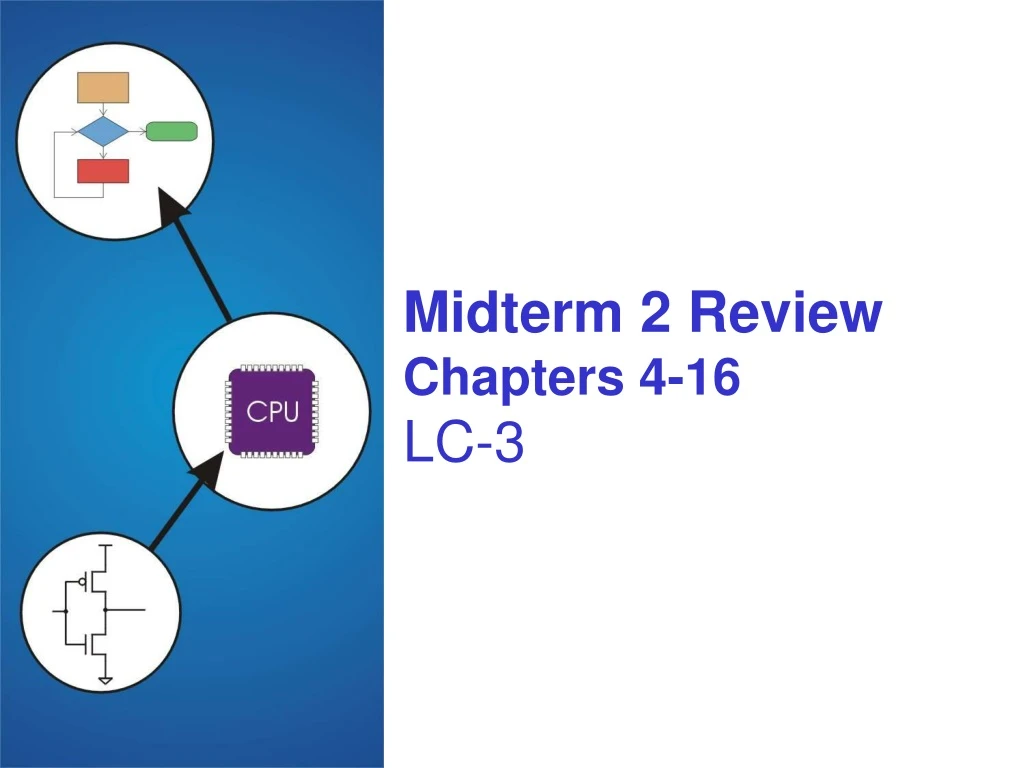
This review covers topics from chapters 4-16 of the LC-3 textbook, including bit width, range of offsets, purpose of registers, instruction basics, 2's complement, interrupts, stacks, hex to instruction, condition codes, instruction cycle, and assembler directives.

E N D
Topics • Bit width • Range of offsets • Purpose of registers • Basics of what the instructions do • 2’s comp • Basics of interrupts • Stacks / stack protocol • Hex to instruction • Condition codes • Instruction cycle • Assembler directives
How many bits are in the IR? • 4 • 3 • 16 • 216 • None of the above
ISAYou will be allowed to use the one page instruction summary.
LC-3 Overview: Instruction Set • Opcodes • 15 opcodes • Operate instructions: ADD, AND, NOT • Data movement instructions: LD, LDI, LDR, LEA, ST, STR, STI • Control instructions: BR, JSR/JSRR, JMP, RTI, TRAP • some opcodes set/clear condition codes, based on result: • N = negative, Z = zero, P = positive (> 0) • Data Types • 16-bit 2’s complement integer • Addressing Modes • How is the location of an operand specified? • non-memory addresses: immediate, register • memory addresses: PC-relative, indirect, base+offset
this one means “immediate mode” ADD/AND (Immediate) Assembly Ex: Add R3, R3, #1 Note: Immediate field issign-extended.
Load and Store instructions Example: LD R1, Label1 R1 is loaded from memory location labelled Label1 Example: LDI R1, Label1 R1 is loaded from address found at location Label1 Example: LDR R1, R4, #1 R1 is loaded from address pointed by R4 with offset 1. Store instructions use the same addressing modes, except the register contents are written to a memory location.
LEA (Immediate) Assembly Ex: LEA R1, Lab1 Used to initialize a pointer.
What instructions would achieve the same result as the LDI instruction below • LEA R2, FAR LD R2, R2, #0 • LEA R2, FAR LDR R2, R2, #0 • LD R2, FAR LDR R2, R2, #0 • LD R2, MAIN LDR R2, R2, #2 • C and D .ORIG x3000 MAIN ADD R2, R2, #3 LDI R2, FAR FAR .FILL xFFFC
Condition Codes • LC-3 has three condition code registers:N -- negativeZ -- zeroP -- positive (greater than zero) • Set by any instruction that writes a value to a register(ADD, AND, NOT, LD, LDR, LDI, LEA) • Exactly one will be set at all times • Based on the last instruction that altered a register Assembly Ex:BRz, Label
What Condition Code is set when the Branch instruction is reached .ORIG x3000 Main LD R1,Twelve LEA R0, Twelve NOT R1,R1 ADD R1,R1,1 ADD R0,R0,R1 BRnzp Main • Twelve .FILL x000C • N • Z • P • Can’t be determined
Assembler Directives • Pseudo-operations • do not refer to operations executed by program • used by assembler • look like instruction, but “opcode” starts with dot
TRAP Instruction • Trap vector • identifies which system call to invoke • 8-bit index into table of service routine addresses • in LC-3, this table is stored in memory at 0x0000 – 0x00FF • 8-bit trap vector is zero-extended into 16-bit memory address • Where to go • lookup starting address from table; place in PC • How to get back • save address of next instruction (current PC) in R7
TRAP NOTE: PC has already been incrementedduring instruction fetch stage.
Given the following segments of LC3 memory what will the PC be loaded with after this instruction has executed? TRAP x21 • x0021 • x0231 • x32AC • xFADC • None of the above
Trap Codes • LC-3 assembler provides “pseudo-instructions” foreach trap code, so you don’t have to remember them.
What is the OUT Trap expecting when it is called • R5 to have the address of a character • R0 to have a characters ASCII value • R5 to have a characters ASCII value • R0 to have the address of a character • None of the above
JSR Instruction • Jumps to a location (like a branch but unconditional),and saves current PC (addr of next instruction) in R7. • saving the return address is called “linking” • target address is PC-relative (PC + Sext(IR[10:0])) • bit 11 specifies addressing mode • if =1, PC-relative: target address = PC + Sext(IR[10:0]) • if =0, register: target address = contents of register IR[8:6]
Example: Negate the value in R0 • 2sComp NOT R0, R0 ; flip bits ADD R0, R0, #1 ; add one RET ; return to caller • To call from a program (within 1024 instructions): • ; need to compute R4 = R1 - R3 ADD R0, R3, #0 ; copy R3 to R0JSR 2sComp ; negate ADD R4, R1, R0 ; add to R1 ... • Note: Caller should save R0 if we’ll need it later!
Why do we need the JSRR instruction • To save the return address in a specific register • To load the PC with a value greater than 256 locations away from the current PC • We don’t it is the same as JMP R7 • To return from an interrupt service routine • None of the above
RET (JMP R7) • How do we transfer control back toinstruction following the TRAP or service/sub routine? • We saved old PC in R7. • JMP R7 gets us back to the user program at the right spot. • LC-3 assembly language lets us use RET (return)in place of “JMP R7”. • Must make sure that service routine does not change R7, or we won’t know where to return.
Memory Usage • Instructions are stored in code segment • Global data is stored in data segment • Local variables, including arrays, uses stack • Dynamically allocated memory uses heap • Code segment is write protected • Initialized and uninitialized globals • Stack size is usually limited • Stack generally grows from higher to lower addresses. 23 23
Basic Push and Pop Code • For our implementation, stack grows downward(when item added, TOS moves closer to 0) • Push R0 • ADD R6, R6, #-1 ; decrement stack ptr STR R0, R6, #0 ; store data (R0) • Pop R0 • LDR R0, R6, #0 ; load data from TOS ADD R6, R6, #1 ; decrement stack ptr • Sometimes a Pop only adjusts the SP. • Arguments pushed onto the stack last to first
What location will the stack pointer point to after this code executes .ORIG x3000 Start JSR Main Main LD R6 Stack LD R3, Start PUSH R1 • ADD R6, R6, #-2 PUSH R3 POP R6 Stack .FILL x4800 • X4801 • X4000 • x47FD • x47FF • A or D
Run-Time Stack Memory Memory Memory R6 R5 Watt R6 R6 R5 R5 main main main Before call During call After call
Activation Record Lower addresses • intNoName(int a, int b){int w, x, y; . . . return y;} y x w dynamic link return address return value a b locals R5 bookkeeping args Name Type Offset Scope a b w x y int int int int int 4 5 0 -1 -2 NoName NoName NoName NoName NoName Compiler generated Symbol table. Offset relative to FP R5
Summary of LC-3 Function Call Implementation • Caller pushes arguments (last to first). • Caller invokes subroutine (JSR). • Callee allocates return value, pushes R7 and R5. • Callee allocates space for local variables. • Callee executes function code. • Callee stores result into return value slot. • Callee pops local vars, pops R5, pops R7. • Callee returns (JMP R7). • Caller loads return value and pops arguments. • Caller resumes computation…
What is not a benefit of using a stack for memory management • Functions only uses memory when they are active • Regions of memory can be marked read only • Data related to one function can be accessed by another function by altering the Frame pointer offset • Implementing of recursion is possible • None of the above
Input from Keyboard • When a character is typed: • its ASCII code is placed in bits [7:0] of KBDR(bits [15:8] are always zero) • the “ready bit” (KBSR[15]) is set to one • keyboard is disabled -- any typed characters will be ignored • When KBDR is read: • KBSR[15] is set to zero • keyboard is enabled keyboard data 15 8 7 0 KBDR 15 14 0 ready bit KBSR
Basic Input Routine POLL LDI R0, KBSRPtr BRzp POLL LDI R0, KBDRPtr ... KBSRPtr .FILL xFE00KBDRPtr .FILL xFE02 new char? NO Polling YES readcharacter
Output to Monitor • When Monitor is ready to display another character: • the “ready bit” (DSR[15]) is set to one • When data is written to Display Data Register: • DSR[15] is set to zero • character in DDR[7:0] is displayed • any other character data written to DDR is ignored(while DSR[15] is zero) output data 15 8 7 0 DDR 15 14 0 ready bit DSR
To implement Memory Mapped IO extra hardware will be needed in the • Processor • Memory Controller • Register File • B and C • None of the above
Interrupt-Driven I/O • External device can: • Force currently executing program to stop; • Have the processor satisfy the device’s needs; and • Resume the stopped program as if nothing happened. • Interrupt is an unscripted subroutine call, triggered by an external event.
Interrupt-Driven I/O • To implement an interrupt mechanism, we need: • A way for the I/O device to signal the CPU that aninteresting event has occurred. • A way for the CPU to test whether the interrupt signal is setand whether its priority is higher than the current program. • Generating Signal • Software sets "interrupt enable" bit in device register. • When ready bit is set and IE bit is set, interrupt is signaled. interrupt enable bit 0 15 14 13 ready bit KBSR interrupt signal to processor
Testing for Interrupt Signal • CPU looks at signal between STORE and FETCH phases. • If not set, continues with next instruction. • If set, transfers control to interrupt service routine. F NO D interrupt signal? YES EA Transfer to ISR OP EX S
Processor State • Must be saved before servicing an interrupt. • What state is needed to completely capture thestate of a running process? • Processor Status Register • Privilege [15], Priority Level [10:8], Condition Codes [2:0] • LC-3: 8 priority levels (PL0-PL7) • Program Counter • Pointer to next instruction to be executed. • Registers • All temporary state of the process that’s not stored in memory. Condition Code Privilege Priority
How does the RTI instruction know if it needs to switch from the supervisor stack to the user stack? • It checks if the priority level of the PSR it pops off the supervisor stack is higher than the current priority level • The RTI instruction does not need to switch between stacks this is the RET instructions responsibility • It checks if the privilege level of the PSR it pops off the supervisor stack is 1 • None of the above