Download
1 / 27
270 likes | 421 Vues
STEVI: Sensory Technology Enhancement for the Visually Impaired. 10/20/2009. Comprehensive Design Review. Team Vouvakis. Electrical and Computer Engineering. The Problem. The visually impaired can not navigate without assistance. Cane People The Guide Dog.

E N D
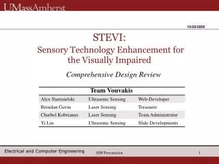
SDP Presentation STEVI:Sensory Technology Enhancement for the Visually Impaired 10/20/2009 Comprehensive Design Review Team Vouvakis Electrical and Computer Engineering
The Problem The visually impaired can not navigate without assistance. • Cane • People • The Guide Dog Electrical and Computer Engineering SDP Presentation 2
Solution - STEVI Electrical and Computer Engineering SDP Presentation 3
SDP Presentation CDR Deliverables • Demonstration of Ultrasonic Detection • Range and Direction up to 4m (Non-Stationary) • Vibrating motors with microcontroller • Demonstration of Laser Detection • Laser and Camera • Microcontroller Processing • Vibrating Motors with microcontroller Electrical and Computer Engineering
Previously Proposed FDR - Block Diagram Electrical and Computer Engineering SDP Presentation 5
FDR Proposed Deliverables – Block Diagram Electrical and Computer Engineering SDP Presentation 6
UDS Design Modifications from MDR Transducers MDR Design: 4x Maxbotix UT CDR Design: 2x Maxbotix LV-EZ4 • Reason for Change: • Previously 4 used (2 Transmit, 2 Receive) Currently pre-assembled transducers on chip can both transmit and receive. • On chip microcontrollers compute distance for individual transducers. Electrical and Computer Engineering SDP Presentation 7
Microcontroller Operation • Synchronizes transducer operation. • Receives distance from transducers & LDS. • Controls Feedback operation. • Switched between LDS & UDS mode. FPR Goals: • Directionality in UDS module. • Range of UDS & LDS simultaneously. Electrical and Computer Engineering SDP Presentation 8
User Feedback System (Vibrating Motors) • Tactile feedback controlled by dsPIC. • Decreasing distance to obstacle increases frequency of vibrating pulses (2/sec at max range, 20/sec at min range. • FPR Goal: Allow for feedback of direction to obstacle. Electrical and Computer Engineering SDP Presentation 9
UDS Test & Analysis: Range Error • Goal: 15cm – 4m range • Achieved: 15cm – 4m range • Limitation: Range error significant for longer distances • Solution: Modify programming to account for error at long ranges Electrical and Computer Engineering SDP Presentation 10
UDS Test & Analysis: Lateral Detection Error • Goal: Detect obstacles within 20º of direction of travel (5cm wide pole used for tests) • Achieved: 26º beam angle at 50cm, 17º beam angle at 100cm, 10º beam angle at 200cm, 8º beam angle at 300cm, 5º beam angle at 400cm • Limitation: Small obstacles difficult to detect at long ranges Electrical and Computer Engineering SDP Presentation 11
UDS Test & Analysis: Obstacle Size Limitation CSA: Obstacle Cross Sectional Area Goal: • Detect object with 25cm2 CSA at all ranges up to 400cm Achieved: • 9cm2 object up to 200cm • 16cm2 object up to 340cm • 25cm2 object at all ranges Electrical and Computer Engineering SDP Presentation 12
LDS Algorithm • Algorithm same as from MDR: • Find brightest pixel in camera’s vision • Use y-coordinate of pixel to calculate distance Electrical and Computer Engineering SDP Presentation 13
LDS Design Modifications from MDR Camera MDR Design: Logitech USB 2.0 MP Camera CDR Design: Camera Mod C3188A-6018 • Reason for Change: • USB camera excessively difficult to integrate with electronics. • New camera small enough for device housing. Electrical and Computer Engineering SDP Presentation 14
LDS Design Modifications from MDR (Cont.) Camera Data Processing MDR Design: Matlab CDR Design: CPLD • Reason for Choice: • CPLD can easily take data synchronously from camera Electrical and Computer Engineering SDP Presentation 15
LDS Design Modifications from MDR (Cont.) Processing Unit MDR Design: Matlab CDR Design: ATMEGA32 16PU • Reason for Choice: • Ease of use for floating point calculations and data transmission Electrical and Computer Engineering SDP Presentation 16
LDS Test & Analysis: Experimental Data • Goal: Detect distance to obstacles up to 3 meters • Achieved: Detection of light-colored obstacles between 0.6 and 2.1 meters
LDS Test & Analysis: Quantization Error • Goal: Reduce Quantization error • Solution: Increase laser-camera separation distance (w) • Limitations: Increases smallest detection distance
Laser Safety • Safety issue: device pointed parallel with ground poses laser hazard • Plan to use three tilt sensors to account for multiple possible orientations of device • Currently working on circuit to prevent tilt sensor activation due to shock or suddent movement Electrical and Computer Engineering SDP Presentation 19
Updated Power Consumption Estimated power consumption reduced, but close to original calculation of 0.8 W. Electrical and Computer Engineering SDP Presentation 20
Weight Estimate STEVI will weigh less than 2 Blackberrys = Electrical and Computer Engineering SDP Presentation 21
Current Budget Update Electrical and Computer Engineering SDP Presentation 22
Summary and Look Ahead Summary: • Better ultrasonic sensor detection • Successful breadboard integration of STEVI prototype FPR Deliverables: • Final STEVI prototype • Sensor fusion algorithm (s) (Implemented in dsPIC) • PCB + housing + sensors + power system Electrical and Computer Engineering SDP Presentation 23
Updated Gantt Chart Electrical and Computer Engineering SDP Presentation 24
Electrical and Computer Engineering SDP Presentation 25
UDS Prototype Detection/Feedback System Control Circuitry Electrical and Computer Engineering SDP Presentation 26
LDS Camera-Laser Separation Testing Electrical and Computer Engineering SDP Presentation 27