Download
1 / 31
310 likes | 489 Vues
Modularity in the Phase II Upgrade of the ATLAS Strip Tracker. Ian Wilmut. Abstract.

E N D
Modularity in the Phase II Upgrade of the ATLAS Strip Tracker Ian Wilmut
Abstract For the phase II upgrade of the ATLAS tracker the Silicon strip tracker will be fully replaced by a larger system, which will need to be accomplished with fewer resources and on a tighter construction and installation schedule than for the current system. One measure to achieve this goal is by the use of modularity throughout the tracker project. Modularity in this context is the use of a number of identical subsystems with simple interfaces to the rest of the system. The modular objects can be produced in dedicated assembly sites and will be fully tested before being used in the next steps of the tracker integration. In this presentation we will illustrate this principle with various examples for modularity throughout the phase II strip tracker project, among which will be the local detector supports (staves/petals), the internal (type I) services and the segmentation of the evaporative cooling plant. We will demonstrate the various advantages this modular approach promises, comparing it with our experiences during the integration of the current ATLAS tracker. We will also discuss the limitations in achieving full modularity due to the finite size, geometry and local non-uniformities of the system and how they can be addressed.
What I will talk about • What Modular and what we mean by modular • Where we are trying to take this approach in the ATLAS Upgrade. Examples: • Service modules • Staves • Cooling plant • What we did before • What we are changing • Benefits of a modular detector • Modular vs common parts • Challenges in modular construction
What the construction industry mean by modular construction. • The construction industry has been exploring modular buildings for many years. • In short, they aim to pre-fabricate building sections off site during the groundwork phase and then assemble the building very quickly. • Building 41 at CERN and Ridgeway House at RAL were both built like this Images from http://www.rollalong.co.uk/ http://www.wikipedia.com/
What has this to do with detectors? • We care about the construction time. • If we rewrite the timeline on the last page for the ATLAS Upgrade it might look like this: R&D and Design FDR and procurement Module assembly Inte Service assembly grat Structure assembly ion Commissioning R&D and Design FDR and procurement Module assembly Integration Commissioning Time Saving Service assembly Structure assembly • We could save significant time building and assembling the detector if we can de-serialise the build. • A modular build could de-centralise the build so we don’t need an army of technicians working abroad for extended periods • A modular build could give us the chance to get really good at making things, rather than “crafting” them each time and knowing what we would do differently next time
What do we mean by modular? • The dictionary doesn’t help that much: • OED “each of a set of standardized parts or independent units that can be used to construct a more complex structure…” • Merrium-Webster “…any in a series of standardized units for use together…” • So for a detector build it suggests that the system is assembled from as few similar systems as possible • This makes sense, and for me is linked very closely to the idea of a learning curve • But for there to be real saving the “modules” must be minimally customised as they are assembled • In the ‘60s Bruce D. Henderson from BCG in Boston (management consultants) started to formalise the idea of a learning curve • In short there are significant savings in construction time as you become familiar with the task the graphs below assume a very modest 20% increase in speed for each doubling of output. • The left hand graph shows the cost/time per item for a single assembly • The graph on the right shows the total cost/time for a system of 1000 assemblies depending on the number of modules in the system • Empirically the SCT build was about here (note item axis values are arbitrary) • Ideally we want the ATLAS upgrade to be here
What we can make modular and how • The modules • We have long and short strip types in the barrel, and 7 types in the endcap • The staves • a structure with 24 or 26 modules upon it • The services • prefabricated into between 20 and 36 units per end • The cooling system • 10 identical cooling plants for two “swappable” spare plants for maintenance/disaster recovery
Modules to structures in the SCT (Barrel) We had 2112 identical barrel modules The services and brackets were laid by hand onto the cylinder The whole cylinder was populated with services The modules were all mounted
Structures to detector on the SCT barrel The populated cylinders are then inserted one into the next and their services opened out.
What we propose for the Upgrade • The cylinders will be exclusively mechanical devices, no services will be laid in before modules are added. • Modules will be installed into a pre-built structure on individual staves containing 26 modules and all the associated services. • Although we will have 12272 (6 x SCT) modules on the barrel we only have to install 472 (0.25 x SCT) staves . • The services no longer need to be integrated/folded out by having a service break at the end of the cylinder
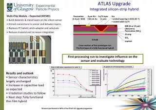
Integrating all the “on cylinder” items • The key design feature of the stave is the combination of modules, cooling, electrical and optical services into one easy to install unit. • All of the services are terminated at the end of the stave. • The stave can be built and tested as a single unit • The stave is a pair of CFRP skins with a carbon foam/honeycomb core, a cooling pipe is embedded in the core. Kapton power tapes run the length of the stave between modules and core.
Real staves • Image on the left is a full size thermo-mechanical prototype with old design locking points • Image below is a 4 module electrical stavelet for electrical testing • Present planning expects we will build staves 13 modules long (1.3m) housing 26 modules.
Stave insertion • Staves can then be slid into the cylinders and locked in place • Once in place the tooling can be removed and the services connected.
Problems with modular staves • One size doesn’t quite fit all • The first problem on a barrel structure is the two ends (ATLAS calls them A and C) C A • So we immediately need A and C end staves • There are other variables as well: • Long and short strips • U and V layers (variation in stereo) • Orientation of locking points • Service connector orientation • To cope with this approach we are proposing a “semi modular” approach
Semi Modular staves • We will build completed staves from kits of parts that allow the stave to be configured for its exact location • We expect 8 variants (long &short strip, A & C ends, U & V stereo) • We hope this “semi-modular” approach will provide the benefits of modularity, but will give us the flexibility required for to meet the physics requirements Temporary PPB0 connection final PPB0 connection final PPB0 connection Final Wire bonds Temporary Wire bonds Temporary PPB0 connection Temporary SMC connection for testing Final SMC Top bus (straight) Bottom bus (+ve or -ve) Top side Top side Bottom side Bottom side
ATLAS Upgrade modular service management PP1 Connectors SM sealing plate CO2 ip/op FO Connectors ID interlink SM Electrical Services Stave cooling pipe (in plane with stave, looped to deal with any movement during thermal contraction, include some electrical break) Stave Stave Connector (mounted to interlink for strain relief)
Installing service modules Close up of pipe work – note the identical structures coming from each service module Mechanical prototype Service Module being offered up to structure mock up Service module in place with possible pipework routing at barrel end
Challenges in service modules design • Our patch panels need to be very compact (i.e. we need a patch panel at the end of the detector) • We have committed to manifolding inside the detector • All the services need a connection at the stave/service module interface • Cooling connections will be orbitaly welded to save mass – modules on staves will be multiplexed on the stave to reduce services • The number of staves per cylinder is not optimal for identical service modules • Service modules need to be able to be configures for a specific location
Detail on the Service Module • We expect between 20 and 36 service modules per end of the detector • They will all be identical and interchangeable • In the event of service failure during the build they will be swapped out not repaired in situ • The cooling pipes will manifold between 8:1 and 8:3 • The electrical cables will be sorted in the service module to deliver combined services at the stave and service types at the ID patch panel • The opto will be sorted in the service module to ensure that any ribbon failures have distributed impact rather than a large local “hole”
Cooling system • Cooling is a critical infrastructure for a tracker at LHC • So far we have discussed modularity in local supports (which typically includes cooling channels/evaporators), and in services, both also part of the cooling system • What about the plant? Can we push the concept of modularity there as well? • Note: the work on the cooling plant in the Tracker upgrade are less developed than other aspects of the tracker
Current ATLAS • Here we will not discuss the various adventures we had with evaporative cooling, but the issue of modularity • One plant to cool SCT and pixels • Design: 70kW at -25°C, 1.1kg/s of C3F8 (6 compressors) • Plant has been installed and commissioned in pit in parallel with ATLAS • For R&D and assembly of detector components smaller plants have been used – which were critically different from final plant • For example single-stage instead of two stage compressors • Some vital lessons could only be learned at a very late stage, the hard way • e.g. mechanical stress on compressors too high in final plant
Evaporative cooling for ATLAS Upgrade • Baseline is CO2, most likely concept 2PACL • Challenge is scaling from existing plants (2kW) to phase II (by factor ~100) • Two steps • Step 1: scale plant capacity by factor ~10 • Step 2: use 10 plants in parallel • Exact distribution to detector not yet decided, probably split into strips and pixels • Would match 10 existing PP2 areas inside ATLAS for close-to-detector distribution • Apart from reducing the technical challenge of scaling, this has other benefits • Cooling plants of the final size/design can be used during assembly and commissioning of tracker subdetectors • This should help us identify any issues with the plant design or other aspects of the cooling system relatively early • Plan to have 2 additional plants as spares/for maintenance • Design for simple interfaces (fluid and control) for fast and arbitrary swap • Complete isolation of circuits in different plants limits damage if something goes seriously wrong (contamination)
Benefits of Modular • Reduce learning time in the build phase of a detector • Make detector elements interchangeable • Failures can be replaced rather than repaired • We can afford to prototype much more of the detector • Less “craft” in detector build • We will need less technician time at CERN for the build, the time will instead be needed at contributing institutes • Full system prototype will be easier and more representative • A prototype with one service module and appropriate staves will be very close to a full system prototype – this will be a very reasonable goal of a system test. • The less items we have to optomise the better we will do • One significant lesson from the SCT is that to many systems were being built for the first time on the real detector
Configurable modules • Detector physics is badly suited to 1000s of identical objects – but it certainly has 10 lots of 100 similar objects • We are aiming to build: • 8 flavours of staves from a standard kit of bits • Up to 72 service modules that can be configured 3 or 4 ways for different locations • 1 structure that can accommodate all of the variations in the staves and service modules • 10 cooling plants that are identical but configured and run for specific loads • Just down the road in Cowley is the Mini plant, they produce 200 000 cars a year (one every 68 seconds) one line produces 5 body styles in any order from a parts list of 6000 parts. • By the definitions I use here a mini is very similar to a set of “configured modules”