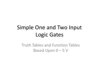
Simple One and Two Input Logic Gates
This resource provides a comprehensive overview of TTL (Transistor-Transistor Logic) input logic gates, including single and double input gates. It covers essential concepts such as truth tables and function tables, where logical "1" corresponds to 5V and logical "0" corresponds to 0V. The document includes detailed analyses of single-input gates like buffers and inverters, as well as two-input gates such as AND, OR, NAND, and NOR. Each gate's symbol and function table are presented for easy reference, making this a valuable guide for students and professionals learning about digital logic design.

Simple One and Two Input Logic Gates
E N D
Presentation Transcript
Simple One and Two InputLogic Gates Truth Tables and Function Tables Based Upon TTL Levels
Assumptions • Truth Tables • True = logical “1” • False = logical “0” • Function Tables • Ideal gate • Output is 0V, which is equivalent to a logical “0” • Output is 5V, which is equivalent to a logical “1”
Single Input Gates: Buffer Symbol Function Table • Truth Table
Single Input Gates: Inverter Symbol Function Table • Truth Table
Two Input Gates: AND Symbol Function Table • Truth Table
Two Input Gates: OR Symbol Function Table • Truth Table
Two Input Gates: NAND Symbol Function Table • Truth Table
Two Input Gates: NOR Symbol Function Table • Truth Table