Logic Gates
Logic Gates. Transistors as Switches. EB voltage controls whether the transistor conducts in a common base configuraiton. Logic circuits can be built. AND. In order for current to flow, both switches must be closed Logic notation A B = C. OR. Current flows if either switch is closed


Logic Gates
E N D
Presentation Transcript
Transistors as Switches • EB voltage controls whether the transistor conducts in a common base configuraiton. • Logic circuits can be built
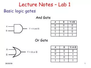
AND • In order for current to flow, both switches must be closed • Logic notation AB = C
OR • Current flows if either switch is closed • Logic notation A + B = C
Properties of AND and OR • Commutation • A + B = B + A • A B = B A Same as Same as
Properties of AND and OR • Associative Property • A + (B + C) = (A + B) + C • A (B C) = (A B) C =
Properties of AND and OR • Distributive Property • A + B C = (A + B) (A + C) • A + B C
Distributive Property • (A + B) (A + C)
Binary Addition Notice that the carry results are the same as AND C = A B
Inversion (NOT) Logic:
Exclusive OR (XOR) Either A or B, but not both This is sometimes called the inequality detector, because the result will be 0 when the inputs are the same and 1 when they are different. The truth table is the same as for S on Binary Addition. S = A B
Getting the XOR Two ways of getting S = 1
Circuit for XOR Accumulating our results: Binary addition is the result of XOR plus AND
Half Adder Called a half adder because we haven’t allowed for any carry bit on input. In elementary addition of numbers, we always need to allow for a carry from one column to the next. 18 25 3 (plus a carry) 4
Chaining the Full Adder Possible to use the same scheme for subtraction by noting that A – B = A + (-B)
Binary Counting Use 1 for ON Use 0 for OFF = 00101011 So our example has 25 + 23 + 21 + 20 = 32 + 8 + 2 + 1 = 43 Binary Counter
Exclusive NOR Equality Detector