LOGIC GATES
LOGIC GATES. INTRODUCTION TO LOGIC GATES. Boolean functions may be practically implemented by using electronic gates. The following points are important to understand. Electronic gates require a power supply.


LOGIC GATES
E N D
Presentation Transcript
LOGIC GATES
INTRODUCTION TO LOGIC GATES • Boolean functions may be practically implemented by using electronic gates. The following points are important to understand. • Electronic gates require a power supply. • Gate INPUTS and OUTPUTS are driven by voltages having two nominal values, e.g. 0V and 5V representing logic 0 and logic 1 respectively. • There is always a time delay between an input being applied and the output responding.
COMPUTER ARCHITECTURE • Truth tables are used to help show the function of a logic gate. • Truth tables help understand the behaviour of logic gates. • They show how the input(s) of a logic gate relate to its output(s). • The gate input(s) are shown in the left column(s) of the table with all the different possible input combinations. This is normally done by making the inputs count up in binary. • The gate output(s) are shown in the right hand side column.
COMPUTER ARCHITECTURE Truth Table Diagram
LOGIC GATES • Digital systems are said to be constructed by using logic gates. • These gates are the: • AND gate • OR gate • NOT gate • NAND gate • NOR gate • EXOR gate • EXNOR gate
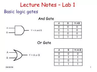
LOGIC GATES - AND The AND gate is an electronic circuit that gives a high output (1) only if all its inputs are high. A dot (.) is used to show the AND operation i.e. A.B. Bear in mind that this dot is sometimes omitted i.e. AB
LOGIC GATES - AND In this animated AND Logic example of Doors Opening and Closing, you can see that in order for the "Light" to get through the house, the front door AND the back door must be Open.
LOGIC GATES - AND Truth Table A & B are the Input switches C is the Output In order for the Output of an AND Logical Function to be TRUE: input (1) ANDinput (2) must both be TRUE. This is Positive Logic. Using the Same Function --It is also correct to say: If either input (1) OR input (2) (or both) is NOT TRUE the Output Will be FALSE. This is Negative Logic. Hint: TRUE is when the switch is closed, applying power to the LED. FALSE is when the switch is open, NOT applying power to the LED)
LOGIC GATES - OR The OR gate is an electronic circuit that gives a high output (1) if one or more of its inputs are high. A plus (+) is used to show the OR operation.
LOGIC GATES - OR In this animated OR Logic example, you can see that in order to get light through the house: the left front door OR the right front door (or both) must be Open. Same example: in order to block the light through the house: the left front door AND the right front door must be Closed.
LOGIC GATES - OR In order for the Output of an OR Logical Function to be TRUE: either input (1) OR input (2) (or both) must be TRUE. This is Positive Logic. Truth Table A & B are the Input switches C is the Output Using the Same Function --It is also correct to say: In order for the Output to be FALSE: input (1) AND input (2) must both be FALSE. This is Negative Logic.
LOGIC GATES - NOT The NOT gate is an electronic circuit that produces an inverted version of the input at its output. It is also known as an inverter. If the input variable is A, the inverted output is known as NOT A. This is also shown as A', or A with a bar over the top, as shown at the outputs.
LOGIC GATES - NAND • This is a NOT-AND gate which is equal to an AND gate followed by a NOT gate. The outputs of all NAND gates are high if any of the inputs are low. The symbol is an AND gate with a small circle on the output. The small circle represents inversion.
LOGIC GATES - NOR • This is a NOT-OR gate which is equal to an OR gate followed by a NOT gate. The outputs of all NOR gates are low if any of the inputs are high. • The symbol is an OR gate with a small circle on the output. The small circle represents inversion.
LOGIC GATES - EXOR • The 'Exclusive-OR' gate is a circuit which will give a high output if either, but not both, of its two inputs are high. An encircled plus sign ( ) is used to show the EOR operation.
LOGIC GATES - EXNOR • The 'Exclusive-NOR' gate circuit does the opposite to the EOR gate. It will give a low output if either, but not both, of its two inputs are high. The symbol is an EXOR gate with a small circle on the output. The small circle represents inversion.
CLASS ACTIVITY 1 A NAND gate can be used as a NOT gate using either of the following wiring configurations. (Check this out using a truth table.)
CLASS ACTIVITY 2 Draw the circuit diagrams to show how a NOR gate can be made into a NOT gate.
CLASS ACTIVITY 2 Draw the circuit diagrams to show how a NOR gate can be made into a NOT gate.
COMPUTER ARCHITECTURE • Drawing Truth Tables for Combined Gates • Truth tables can also help understand the behaviour of combinations of logic gates linked together. • They are drawn in the same way as before but this time adding more columns in between the input and output columns. • Each of the new columns show the outputs of stages in the logic circuit. • The following example shows the steps for drawing up a truth table for a combined gate.