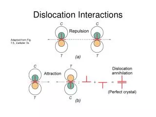
Dislocation Interactions
Dislocation Interactions. Adapted from Fig. 7.5, Callister 7e. Lattice Stress Fields at Dislocations. Adapted from Fig. 7.4, Callister 7e. Ashby model (left) Disassemble polycrystal Allow each to deform according to Schmid’s law – create statistically stored dislocations

Dislocation Interactions
E N D
Presentation Transcript
Dislocation Interactions Adapted from Fig. 7.5, Callister 7e.
Lattice Stress Fields at Dislocations Adapted from Fig. 7.4, Callister 7e.
Ashby model (left) Disassemble polycrystal Allow each to deform according to Schmid’s law – create statistically stored dislocations Creates overlaps and voids “Correct” overlaps with geometrically necessary dislocations until grains fit together again Reassemble crystal Polycrystalline Slip G. Dieter, Mechanical Metallurgy, 3rd Edition, McGraw-Hill, 1986.
Slip Motion in Polycrystals s 300 mm • • Stronger - grain boundaries pin deformations • • Slip planes & directions • (l, f) change from one • crystal to another. • • tRwill vary from one • crystal to another. • • The crystal with the • largest tR yields first. • First crystals to yield increase stress on surrounding crystals • • Other (less favorably • oriented) crystals • yield later. Adapted from Fig. 7.10, Callister 7e. (Fig. 7.10 is courtesy of C. Brady, National Bureau of Standards [now the National Institute of Standards and Technology, Gaithersburg, MD].)
Strengthening Mechanisms • What is STRENGTH? • Ability of the material to resist deformation under applied stress • How do metal crystals deform – they shear by dislocation motion • Therefore: Anything that prevents or slows dislocation motion – increases strength
Present 5 Strengthening Mechanisms • Reduction in Grain Size • Substitutional Solid Solution Strengthening • Interstitial Solid Solution Strengthening • Cold Work • Precipitation Strengthening Note: All of these are generally operative only at temperatures below 0.5Tm (K)
Grain Boundaries High angle grain boundary represents a region of random misfit between adjoining crystals • • In a polycrystalline material continuity must be maintained • Considerable differences in the amount of deformation (dislocation density) between grains and across a single grain • More slip systems typically operate near the grain boundary because of the increased strain • Grain boundaries are dislocation sources • Fine grained materials have greater strain hardening Hall-Petch Equation: G. Dieter, Mechanical Metallurgy, 3rd Edition, McGraw-Hill, 1986.
Solid Solution Strengthening A C D B • • Impurity atoms distort the lattice create local stress fields • Dislocations also contain local stress fields • Interaction of these stress fields impedes dislocation motion
Solute Alloying Additions • The typical effect of solute additions is to raise the yield stress and the level of the stress strain curve as a whole. • Affect the entire stress-strain curve – solute atoms influence the frictional resistance to dislocation motion rather than static locking of dislocations. • Solute atoms fall into 2 broad categories: • Atoms which produce non-spherical distortions – interstitials – strengthening • effect (per unit concentration) is 3G (shear modulus) • Atoms which produce spherical distortion – substitutional atoms – G/10 G. Dieter, Mechanical Metallurgy, 3rd Edition, McGraw-Hill, 1986.
Interstitial Strengthening • Highly mobile interstitial impurities tend to concentrate at dislocations (Cottrell Atmospheres) • Reduce mobility of dislocation increase strength Note: Responsible for discontinuous yielding
180 400 120 Yield strength (MPa) Tensile strength (MPa) 300 60 200 0 10 20 30 40 50 0 10 20 30 40 50 wt.% Ni, (Concentration C) wt.%Ni, (Concentration C) Ex: Solid Solution Strengthening in Copper • Tensile strength & yield strength increase with wt% Ni. Adapted from Fig. 7.16 (a) and (b), Callister 7e. • Empirical relation: • Alloying increases sy and TS.
force -Forging -Rolling roll die A d A A A o blank o d Adapted from Fig. 11.8, Callister 7e. roll force -Drawing -Extrusion A o die container A d die holder tensile force A o ram A billet extrusion d force die die container Cold Work (%CW) • Room temperature deformation. • Common forming operations change the cross sectional area:
total dislocation length unit volume Plastic Deformation • Plastic deformation produces an increase in the number of dislocations Dislocation density = An annealed metal (undeformed) : 106 - 108 dislocations per cm2 A severely plastically deformed metal: 1012 dislocations per cm2 Most of the energy expended during cold working is converted to heat Roughly 10% is stored in the lattice as increased internal energy (.01 – 1 cal/g) G. Dieter, Mechanical Metallurgy, 3rd Edition, McGraw-Hill, 1986.
Dislocations During Cold Work 0.9 mm • Ti alloy after cold working: • • As the concentration of dislocations increases • Dislocations interact and obstruct one another. (Spaghetti) • • Dislocation motion becomes more difficult.