Download

1 / 37
370 likes | 562 Vues
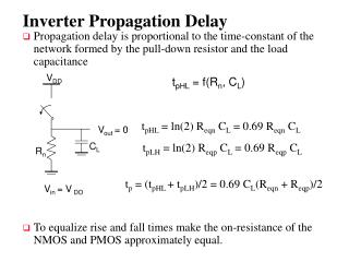
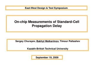
Effects of Inductance on the Propagation Delay and Repeater Insertion in VLSI Circuits. Yehea I. Ismail and Eby G. Friedman , Fellow, IEEE. Agenda. Introduction Propagation Delay Formula Comparison to an RC Model Dependence of Delay on wire Length Repeater Insertion for an RLC Interconnect

E N D
Effects of Inductance on the Propagation Delayand Repeater Insertion in VLSI Circuits Yehea I. Ismail and Eby G. Friedman, Fellow, IEEE
Agenda • Introduction • Propagation Delay Formula • Comparison to an RC Model • Dependence of Delay on wire Length • Repeater Insertion for an RLC Interconnect • Conclusions
The transfer function- a lossy transmission line Zs is source impedance, ZL is load impedance γ is propagation constant, Z0 is characteristic impedance
The parameter ζ Three parameter:ζ,RT,CT
Laplace transform-3 The scaled 50% propagation delay t`pd can be calculated by solving Thus, the propagation delay of an RCL line with a source Resistance Rtr and a load capacitance CL has the form
AS/X [20] simulations the maximum error is 4.6% and the average error is 1.65%
AS/X [20] simulations Eq.(18):
Delay function is more accurate When CT And RT are high and ζ is low Eq(18) suffers high errors This case can only occur for unreasonably high values of the inductance per unit length of the line as compared to the resistance and capacitance per unit length Such a case does not exist in a practical VLSI circuit.
Dependence of Delay on Interconnect Length αasym is the asymptotic value at high frequencies of the attenuation per unit length of the signals L 0 tpd =0.37RCl2 R 0 tpd = l(LC)0.5
Repeater Insertion for an RLC Interconnect The buffer output impedance Rtr is R0/h The input capacitance of the buffer CL is hC0
highly accurate The error is less than 0.05% If Lt 0 hopt(RLC) = hopt(RC) kopt(RLC) = kopt(RC)
Total delay in RC & RLC When TL/R=3 ,tpdtotal increase by 10% When TL/R=5 ,tpdtotal increase by 20% When TL/R=10 ,tpdtotal increase by 30%
Area in RC & RLC Amin is the area of a minimum size buffer = When TL/R=3 ,Area increase by 154% When TL/R=5 ,Area increase by 435%
conclusion • Propagation delay --- 35% • propagation delay has linear dependence on the length of the line.
Conclusion for repeater insertion • Insert less buffer • Reduce delay • Reduce buffer area