Inductance and AC Circuits
820 likes | 1.93k Vues
Inductance and AC Circuits. Mutual Inductance Self-Inductance Energy Stored in a Magnetic Field LR Circuits LC Circuits and Electromagnetic Oscillations LC Circuits with Resistance ( LRC Circuits) AC Circuits with AC Source. LRC Series AC Circuit Resonance in AC Circuits

Inductance and AC Circuits
E N D
Presentation Transcript
Mutual Inductance • Self-Inductance • Energy Stored in a Magnetic Field • LR Circuits • LC Circuits and Electromagnetic Oscillations • LC Circuits with Resistance (LRC Circuits) • AC Circuits with AC Source
LRC Series AC Circuit • Resonance in AC Circuits • Impedance Matching • Three-Phase AC
Ch. 32 Exer. 3, 4, 5, 6, 9, 10, 11, 12, Homework
Induced emf in one circuit due to changes in the magnetic fieldproduced by the second circuit is called mutual induction. Induced emf in one circuit associated with changes in its own magnetic fieldis called self-induction. Inductance
Inductance Unit of inductance: the henry, H: 1 H = 1 V·s/A = 1 Ω·s.
Mutual Inductance Mutual inductance: magnetic flux through coil2 due to current in coil 1 Induced emf due to mutual induction:
Mutual Inductance Solenoid and coil. A long thin solenoid of length l and cross-sectional area A contains N1 closely packed turns of wire. Wrapped around it is an insulated coil of N2 turns. Assume all the flux from coil 1 (the solenoid) passes through coil 2, and calculate the mutual inductance.
Mutual Inductance Reversing the coils. How would the previous example change if the coil with turns was inside the solenoid rather than outside the solenoid?
Self-Inductance Self-inductance: magnetic flux through the coil due to the current in the coil itself: A changing current in a coil will also induce an emf in itself:
Self-Inductance Solenoid inductance. (a) Determine a formula for the self-inductance L of a tightly wrapped and long solenoid containing N turns of wire in its length l and whose cross-sectional area is A. (b) Calculate the value of L if N = 100, l = 5.0 cm, A = 0.30 cm2, and the solenoid is air filled.
Self-Inductance Direction of emf in inductor. Current passes through a coil from left to right as shown. (a) If the current is increasing with time, in which direction is the induced emf? (b) If the current is decreasing in time, what then is the direction of the induced emf?
Self-Inductance Coaxial cable inductance. Determine the inductance per unit length of a coaxial cable whose inner conductor has a radius r1 and the outer conductor has a radius r2. Assume the conductors are thin hollow tubes so there is no magnetic field within the inner conductor, and the magnetic field inside both thin conductors can be ignored. The conductors carry equal currents I in opposite directions.
Ch. 32 Exer. 17, 18, 19, 23, 24, 25, Exer. 28, 29, 30, 34, 35, 36, Exer. 37, 38, 39, 40, Prob. 5, 10, Homework
LR Circuits A circuit consisting of an inductor and a resistor will begin with most of the voltage drop across the inductor, as the current is changing rapidly. With time, the current will increase less and less, until all the voltage is across the resistor.
LR Circuits . If the circuit is then shorted across the battery, the current will gradually decay away:
LR Circuits An LR circuit. At t = 0, a 12.0-V battery is connected in series with a 220-mH inductor and a total of 30-Ω resistance, as shown. (a) What is the current at t = 0? (b) What is the time constant? (c) What is the maximum current? (d) How long will it take the current to reach half its maximum possible value? (e) At this instant, at what rate is energy being delivered by the battery, and (f) at what rate is energy being stored in the inductor’s magnetic field?
Energy Density of a Magnetic Field Just as we saw that energy can be stored in an electric field, energy can be stored in a magnetic field as well, in an inductor, for example. Analysis shows that the energy density of the field is given by
Energy Stored in an Inductor The equation governs the LR circuit is Multiplying each term by the current i leads to
Energy Stored in an Inductor Therefore, the third term represents the rate at which the energy is stored in the inductor The total energy stored from i=0 to i=I is
Energy Density of a Magnetic Field The self-inductance of a solenoid is L=μ0nA2l. The magnetic field inside it is B=μ0nI. The energy stored thus is Since Al is the volume of the solenoid, the energy per volume is This is the energy density of a magnetic field in free space.
LC Circuits and Electromagnetic Oscillations An LC circuit is a charged capacitor shorted through an inductor.
LC Circuits Across the capacitor, the voltage is raised by Q/C. As the current passes through the inductor, the induced emf is –L(dI/dt). The Kirchhof’s loop rule gives The current causes the charge in the capacitor to decreases so I=-dQ/dt. Thus the differential equation becomes
LC Circuits and Electromagnetic Oscillations The equation describing LC circuits has the same form as the SHO equation: The charge therefore oscillates with a natural angular frequency .
Electromagnetic Oscillations The charge varies as The current is sinusoidal as well: Remark: When Q=Q0 at t=t0, we have φ=0.
LC Circuits and Electromagnetic Oscillations The charge and current are both sinusoidal, but with different phases.
LC Circuits and Electromagnetic Oscillations The total energy in the circuit is constant; it oscillates between the capacitor and the inductor:
LC Circuits and Electromagnetic Oscillations LC circuit. A 1200-pF capacitor is fully charged by a 500-V dc power supply. It is disconnected from the power supply and is connected, at t = 0, to a 75-mH inductor. Determine: (a) the initial charge on the capacitor; (b) the maximum current; (c) the frequency f and period T of oscillation; and (d) the total energy oscillating in the system.
LRC Circuits Any real (nonsuperconducting) circuit will have resistance.
LRC Circuits Adding a resistor in an LC circuit is equivalent to adding –IR in the equation of LC oscillation Initially Q=Q0, and the switch is closed at t=0, the current is I=-dQ/dt. The differential equation becomes
LRC Circuits The equation describing LRC circuits now has the same form as the equation for the damped oscillation: The solution to LRC circuits therefore is
LRC Circuits The damped angular frequency is where ω02=1/LC. The system will be underdamped for R2 < 4L/C, and overdamped for R2 > 4L/C. Critical damping will occur when R2 = 4L/C.
LRC Circuits This figure shows the three cases of underdamping, overdamping, and critical damping.
LRC Circuits Damped oscillations. At t = 0, a 40-mH inductor is placed in series with a resistance R = 3.0 Ω and a charged capacitor C = 4.8 μF. (a) Show that this circuit will oscillate. (b) Determine the frequency. (c) What is the time required for the charge amplitude to drop to half its starting value? (d) What value of R will make the circuit nonoscillating?
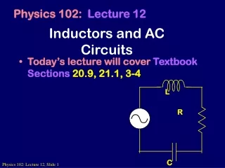
30-7 AC Circuits with AC Source Resistors, capacitors, and inductors have different phase relationships between current and voltage when placed in an ac circuit. The current through a resistor is in phase with the voltage.
30-7 AC Circuits with AC Source . The voltage across the inductor is given by or Therefore, the current through an inductor lags the voltage by 90°.
30-7 AC Circuits with AC Source . The voltage across the inductor is related to the current through it: The quantity XL is called the inductive reactance, and has units of ohms:
30-7 AC Circuits with AC Source Example 30-9: Reactance of a coil. A coil has a resistance R = 1.00 Ω and an inductance of 0.300 H. Determine the current in the coil if (a) 120-V dc is applied to it, and (b) 120-V ac (rms) at 60.0 Hz is applied.
30-7 AC Circuits with AC Source . The voltage across the capacitor is given by Therefore, in a capacitor, the current leads the voltage by 90°.
30-7 AC Circuits with AC Source . The voltage across the capacitor is related to the current through it: The quantity XC is called the capacitive reactance, and (just like the inductive reactance) has units of ohms:
30-7 AC Circuits with AC Source Example 30-10: Capacitor reactance. What is the rms current in the circuit shown if C = 1.0 μF and Vrms = 120 V? Calculate (a) for f = 60 Hz and then (b) for f = 6.0 x 10⁵ Hz.
30-7 AC Circuits with AC Source This figure shows a high-pass filter (allows an ac signal to pass but blocks a dc voltage) and a low-pass filter (allows a dc voltage to be maintained but blocks higher-frequency fluctuations).
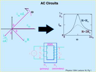
30-8 LRC Series AC Circuit Analyzing the LRC series AC circuit is complicated, as the voltages are not in phase – this means we cannot simply add them. Furthermore, the reactances depend on the frequency.
30-8 LRC Series AC Circuit We calculate the voltage (and current) using what are called phasors – these are vectors representing the individual voltages. Here, at t = 0, the current and voltage are both at a maximum. As time goes on, the phasors will rotate counterclockwise.