Download

1 / 24
240 likes | 389 Vues
Chapter 33 Inductance, Electromagnetic Oscillations, and AC Circuits Part II. AC Circuits with AC Source. Resistors, capacitors, and inductors have different phase relationships between current and voltage when placed in an ac circuit.

E N D
Chapter 33Inductance, Electromagnetic Oscillations, and AC CircuitsPart II
AC Circuits with AC Source Resistors, capacitors, and inductors have different phase relationships between current and voltage when placed in an ac circuit. The current through a resistor is in phase with the voltage.
AC Circuits with AC Source . The voltage across the inductor is given by or Therefore, the current through an inductor lags the voltage by 90°.
AC Circuits with AC Source . The voltage across the inductor is related to the current through it: The quantity XL is called the inductive reactance, and has units of ohms:
AC Circuits with AC Source Example : Reactance of a coil. A coil has a resistance R = 1.00 Ω and an inductance of 0.300 H. Determine the current in the coil if (a) 120-V dc is applied to it, and (b) 120-V ac (rms) at 60.0 Hz is applied.
AC Circuits with AC Source . The voltage across the capacitor is given by Therefore, in a capacitor, the current leads the voltage by 90°.
AC Circuits with AC Source . The voltage across the capacitor is related to the current through it: The quantity XC is called the capacitive reactance, and (just like the inductive reactance) has units of ohms:
AC Circuits with AC Source Example : Capacitor reactance. What is the rms current in the circuit shown if C = 1.0 μF and Vrms = 120 V? Calculate (a) for f = 60 Hz and then (b) for f = 6.0 x 10⁵ Hz.
AC Circuits with AC Source This figure shows a high-pass filter (allows an ac signal to pass but blocks a dc voltage) and a low-pass filter (allows a dc voltage to be maintained but blocks higher-frequency fluctuations).
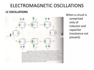
LRC Series AC Circuit Analyzing the LRC series AC circuit is complicated, as the voltages are not in phase – this means we cannot simply add them. Furthermore, the reactances depend on the frequency.
LRC Series AC Circuit We calculate the voltage (and current) using what are called phasors – these are vectors representing the individual voltages. Here, at t = 0, the current and voltage are both at a maximum. As time goes on, the phasors will rotate counterclockwise.
LRC Series AC Circuit Some time t later, the phasors have rotated.
LRC Series AC Circuit The voltages across each device are given by the x-component of each, and the current by its x-component. The current is the same throughout the circuit.
LRC Series AC Circuit We find from the ratio of voltage to current that the effective resistance, called the impedance, of the circuit is given by
LRC Series AC Circuit The phase angle between the voltage and the current is given by or The factor cos φ is called the power factor of the circuit.
LRC Series AC Circuit Example 30-11: LRC circuit. Suppose R = 25.0 Ω, L = 30.0 mH, and C = 12.0 μF, and they are connected in series to a 90.0-V ac (rms) 500-Hz source. Calculate (a) the current in the circuit, (b) the voltmeter readings (rms) across each element, (c) the phase angle , and (d) the power dissipated in the circuit.
Resonance in AC Circuits The rms current in an ac circuit is Clearly, Irms depends on the frequency.
Resonance in AC Circuits We see that Irms will be a maximum when XC = XL; the frequency at which this occurs is f0 = ω0/2π is called the resonant frequency.
Impedance Matching When one electrical circuit is connected to another, maximum power is transmitted when the output impedance of the first equals the input impedance of the second. The power delivered to the circuit will be a minimum when dP/dt = 0; this occurs when R1 = R2.
Three-Phase AC Transmission lines usually transmit three-phase ac power, with the phases being separated by 120°. This makes the power flow much smoother than if a single phase were used.
Three-Phase AC Example : Three-phase circuit. In a three-phase circuit, 266 V rms exists between line 1 and ground. What is the rms voltage between lines 2 and 3?
Summary of Chapter • Mutual inductance: • Self-inductance: • Energy density stored in magnetic field:
Summary of Chapter . . • LR circuit: • Inductive reactance: • Capacitive reactance:
Summary of Chapter . • LRC series circuit: • Resonance in LRC series circuit: