Verilog Programming Basics: Random Number Generation and Module Design
This guide covers essential Verilog programming techniques, including random number generation, module design, and testing with example implementations. It highlights observations from recent lab sessions, offering corrections and troubleshooting tips. Notably, it shows how to utilize `include` files, structure Verilog modules, and implement logical functions using NAND gates. The document also provides insights into creating test benches that feed random sequences of binary numbers to modules. Learn about the significance of timing, correct syntax, and module functionality for effective Verilog programming.

Verilog Programming Basics: Random Number Generation and Module Design
E N D
Presentation Transcript
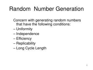
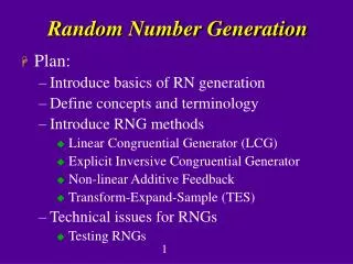
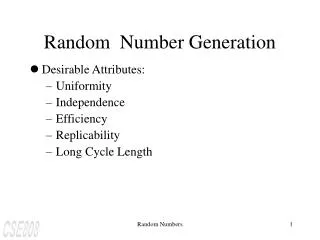
Random Number Generation Section 3.10 Section 4.12
Outline • Observations from the last week’s lab • Anatomy of a Verilog Program • More about Verilog • Including a file • Test a Module with a Random Sequence • Example: NAND Implementation of a NOT Gate • The NAND Implementation of a NOR Gate • Implementation Using 74LS00
Observations from Last Thursday’s Lab (1) • The verilog code should be saved in a *.v file, e.g. • fig3p37.v is the file name • to execute the simulation, you need to type verilog +gui fig3p37.v &
Observations from Last Thursday’s Lab (2) Correction: Remove semicolon from the end of timescale line.
Observations from Last Thursday’s Lab (3) Correction: Use a backward quote (`), not a single quote (‘)
Observations from Last Thursday’s Lab (4) fig3p37 is the module name. I1 is the instance of the module. Comment: You need both modules! Definition of the module
Observations from Last Thursday’s Lab (5) System! Source file "fig3p37.v" cannot be opened for reading [Verilog-SFCOR] Solution: [r2d2@localhost verilogSandBox]$ chmod 755 fig3p37.v
Question // comments out a line
Question: How do I get the play button back? If you comment out $stop and stop the simulation by using Initial #200 $finish, you will not get the play button. What do you do then?
Solution: Simulation ->Reinvoke Simulator Select Yes
You Get the Play Button Back! Play button
Review of What We have Learned • A minimalist’s view of a verilog Module • A minimalist’s view of a module test bench
Anatomy of a Verilog Module module fig3p37 (A,B,C,D,E); output D,E; input A,B,C; wire w1; and G1(w1,A,B); not G2(E,C); or G3(D,w1,E); endmodule
module....endmodule module fig3p37 (A,B,C,D,E); output D,E; input A,B,C; wire w1; and G1(w1,A,B); not G2(E,C); or G3(D,w1,E); endmodule Always start the verilog program with the keyword pair module…endmodule The keyword module must always be terminated by the keyword endmodule.
output/input module fig3p37 (A,B,C,D,E); output D,E; input A,B,C; wire w1; and G1(w1,A,B); not G2(E,C); or G3(D,w1,E); endmodule output/input wire
Program Body module fig3p37 (A,B,C,D,E); output D,E; input A,B,C; wire w1; and G1(w1,A,B); not G2(E,C); or G3(D,w1,E); endmodule Program body
Anatomy of a Test Bench Test Bench `timescale module module_tb (, , ,)…endmodule ouput,reg Invoke the module Define the input vector
Use `include to reference a file Troubleshooting Exercise: verilog +gui fig3p37.v &
Introduce a Random Test Vector • flip_me function Q: What is the function of this module?
flip_me_tb.v • Test Bench Definition: Feed a random sequence of binary numbers to flip_me.v A=random input B=flipped version of A
Test Bench for flip_me.v Reference: Mano page 170-174.
`timescale Comment out time scale Each time interval is one second.
Define outputs,reg We will read random numbers from a file. The random numbers are stored in t_A. vectornum is the index of the t_A. At the falling edge of the t_clock, a random numbers stored in t_A is transferred to A.
Clock Generation t_clock is initially 0. t_clock is flipped every 5 time intervals. The period of t_clock is 10 time intervals.
Read numbers from an input file Random number is stored in t_A.
Update at NegEdge of t_clock At negative edge of t_clock, transfer the random number from t_A to A.
Monitor Numbers Monitor numbers
Run Verilog Using Command-line $monitor only displays the results when A changes. Actual sequence: 101011001011…
Implement NOR with NANDs G1 E C F G3 G4 D G2 A, B as inputs C,D, E as wires F as output
nor_with_nand_tb.v Use flip_me_tb.v as a guide. Complete the code for nor_with_nand_tb.v