Download

1 / 36
360 likes | 397 Vues
Explore the mechanics of joint function and material properties in the human body, from artificial hips to bending and torsion theories. Understand forces, moments, stress, strain, and viscoelasticity. Learn how materials respond to loading, fatigue, and failure. Discover the principles behind biomechanical modeling and simulation techniques.

E N D
Artificial hips Chapter 3 - Joint and Materials Mechanics Shoe impact tester
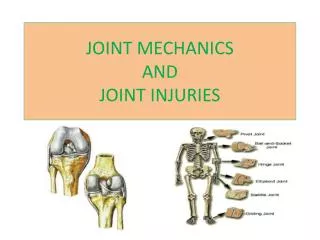
Joint Motion • Anatomical Position • Planes • Sagittal • Frontal • Transverse
Mobility and ROM • ROM joint & person specific • Injuries: excessive ROM • Factors affecting ROM: • Shape and geometry of articulating surfaces • Joint capsule and ligaments • Surrounding muscles • Apposition of body parts • Joint Stability
Lever Systems R F • Rigid rod fixed at point to which two forces are applied • 1st class • 2nd class • 3rd class • Functions • applied force • effective speed F R R F
Instantaneous Joint Center • Caused by asymmetries in the joint motion • Basic movements • rotation • sliding • rolling
Moment of Force & Joint Motion • Moment = F ·d • Moment = muscular activity, essential for controlling joint motion • Theory: actions at joints can be represented by the resultant joint force and the resultant joint moment
Resultant Joint Force vs Bone-on-Bone Forces • RJF: Net force across the joint produced by bone, ligaments, muscle etc. • Bone-on-Bone: more complex calculation
Material Mechanics • Rigid body mechanics: body segments are considered rigid structures (non-deformable) • fixed center of mass • homogeneous material • Used to analyze movements • Easier to model and provide a reasonable approximation
Deformable solids • Segment or tissue analyzed undergoes deformation • More complicated analysis and difficult to model
Material Properties • Basic properties • Size • Shape • Area • Volume • Mass • Derived • Density • Centroid
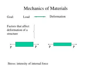
Stress • Stress (): internal resistance to an external load • Axial (compressive or tensile) =F/A • Shear = F/A (parallel or tangential forces) • Units Pascal (Pa) = 1Nm2 Axial Shear
Strain • Change in shape or deformation () • Absolute strain • Relative strain • L/Lo
Stress &Strain • Stress-strain ratio: stiffness or compliance of the material • E = / • Linear material • Hooke’ law: = E· • Biological material non-linear due to its tissue fluid component (viscoelastic properties) A B
Uniaxial Loading E • Simplest form: forces applied along single line typically the primary axis • compressive • tensile • shear • Stress-strain curve • Linear region (B) • elastic limit (C) • yield point (D) • ultimate stress (E) • Rupture (F) • Energy stored (area) D F C B
Poisson’s effect Force • When a body experiences an uniaxial load its axial & transverse dimensions will change, • v = -(t/ a)
Multiaxial Loading • Deformation in all three directions • Net effect of the strains • Shear stresses
Bending • Long bones: beams • Compressive stress: inner portion • Tensile stress: outer portion • Max stresses near the edges, less near the neutral axis T C axis axis y x=(Mb·y)/I
Bending Moments • Shear stresses max at neutral axis and zero at the surface • = (Q·V)/(I ·b) • Q= area moment • V= vertical shear force Q y h b
Bending • Three point bending • failure at middle • ski boot fracture • Four point bending • failure at the weakest point between two inside forces
Bending • Cantilever bending • Compressive force acting off-center from long axis
Torsion • Twisting action applied to a structure • Resistance about long axis determined by polar moment of inertia • J=[·(r4o-r4i)]/2 • Shear stress along the shaft =(T·r)/J • Twist angle: =(T·l)/(G·J)
Torsion • Larger radius of the shaft, greater resistance • Stiffer the material harder to deform • In addition to shear stress, normal stress (tensile & compressive) are produced in a helical path (spiral fractures) r
Viscoelasticity • Provided by the fluid component in biological tissue • Resistance to flow • Affects stress-strain • Increase in strain rate produces-increases stiffness of the material
Viscoelasticity • Pure elastic material • strain energy returned • no energy loss • Viscoelastic tissues • lose energy due to heat • energy is not returned immediately • Resilient • Dampened • Hysteresis: area representing energy lost Elastic Load Non unload
Viscoelasticity creep • Creep response • Stress-relaxation response • Effects of strain-rate on stress relaxation Time
Material Fatigue & Failure Initial cycle effect • Fatigue: repeated loads above a certain threshold • Continued loading: failure • First cycle effect: shift in mechanical response 1 2 3 n
Material failure • Distribution of stresses • Discontinuity (stress risers) • fractures sites • screws • osteotendinous junctions • Ductile vs Brittle materials • Failure theories • maximal normal stress • maximal shear stress • maximal energy distortion
Biomechanical Modeling & Simulation • Model: representation of one or more of an object’s or system’s characteristics using mathematical equations • Goal • improve understanding of a system • Simulation:process of using validated model
Biomechanical Modeling & Simulation • Physical model: simulates actual conditions, crash test dummies • Mathematical or computer model: conditions are represented using mathematical equations
Why use a model? • Easy to duplicate • Easy to make change in the system • Time • Economic factor
What questions is being posed? Type: molecular, tissue, organ etc. Deformable or rigid finite or continuoum static, quasi static or dynamic Linear or nonlinear 2D or 3D Determined or stochastic kinematics or kinetics inverse or direct How to select a model?
Model & Simulations • Models are simplifications of actual situations • Model and simulation are as good as the data use as input • Stability of the model (range of values)
Finite-element modeling • Structures are represented as simple blocks assembled to form complex geometrical structures • Connected at poinst (nodes) forming a mathetical representation of the structure • Forces are applied at the structure and stress and strain are predicted • Complex and requires a great deal of computing power
Rheological Models • Study of deformation and flow of matter • Use to model biological tissue • Interrelate stress, strain, and strain rate • Three types • Linear spring • dashpot • frictional • Linear spring • elastic properties of tissue
Rheological Models • Dashpot • loading response that is strain rate dependent • fluid viscosity (newtonian fluid) • = · • Frictional element • Combinations of models Strain rate