Download
1 / 87
940 likes | 1.35k Vues
Radar Meteorology. Theoretical work (Mie scattering theory) in the late 1940s showed that “weather clutter” arose from the scattering of electromagnetic radiation by precipitation particles (resonant interaction between propagating EM wave and a dielectric such as water and ice).

E N D
Radar Meteorology Theoretical work (Mie scattering theory) in the late 1940s showed that “weather clutter” arose from the scattering of electromagnetic radiation by precipitation particles (resonant interaction between propagating EM wave and a dielectric such as water and ice). Today modern radars can not only detect hydrometeors (both precipitation and cloud particles), but “clear air” targets such as insects and large aerosol particles, as well as changes in the index of refraction, the latter caused by turbulent motions in the atmosphere.
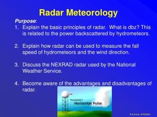
RADAR-Radio Detection and Ranging Radar is the “art of detecting by means of radio echoes the presence of objects, determining their direction and range, recognizing their characteristics and employing the data thus obtained”. “Object” refers to meteorological targets such as raindrops, hailstones, cloud ice and liquid particles and snowflakes. For the purpose of clear air detection, insects are considered the “objects”. Birds also are readily detected and hence are of interest. Radar is based on the propagation of electromagnetic waves through the atmosphere, a non-vacuum. EM waves propagate at the speed of light in a vacuum, c = 2.998 x 10⁸ m s-1. Propagation speed in a non-vacuum determines the index of refraction, n = c/νwhere ν is the wave speed (Note : water and ice have different refractive index)
Electromagnetic Waves and Their Propagation Through the Atmosphere
Electromagnetic Waves are characterized by: Wavelength, λ [m, cm, mm, mm etc] Frequency, ν [s-1, hertz (hz), megahertz (Mhz), gigahertz (Ghz) where: c = λν
Polarization of electromagnetic waves The polarization is specified by the orientation of the electromagnetic field. The plane containing the electric field is called the plane of polarization.
Electric field will oscillate in the x,y plane with z as the propagation direction For a monochromatic wave: where f is the frequency and d is the phase difference between Exm and Eym and the coordinate x is parallel to the horizon, y normal to x, and z in the direction of propagation. If Eym = 0, Electric field oscillates in the x direction and wave is said to be “horizontally polarized” If Exm = 0, Electric field oscillates in the y direction and wave is said to be “vertically polarized” If Exm = Eym, and d = π/2 or - π/2, electric field vector rotates in a circle and wave is circularly polarized All other situations: E field rotates as an ellipse
How does radar scan ? Ground/ship radar
Scanning strategies for scanning radars must take into account the propagation path of the beam if certain operational or scientific objectives are to be addressed. Here, 3 common NWS NEXRAD Volume Coverage Patters (VCPs) are illustrated. NEXRADs have a 5-6 minute scan update requirement for severe weather detection, so they vary their VCPs and scan rates depending on the weather situation. VCP 31 “clear air mode” 6 min update, slow scan rate VCP 11 “severe weather mode” 5 min update, fast scan rate VCP 21 Wide-spread precip 6 min update, slow scan rate
Airborne Commercial airplanes
Airborne Research airplanes
What kind of electromagnetic pulse do we send?
Antenna Transmitter 106 W Block Diagram of a Radar System Display T/R switch Receiver 10-14 W
Why is wavelength important? • Longer wave length -> sensitive to larger objects -> larger penetration ability (long range), but require a larger antenna to obtain enough return signal • Shorter wave length -> sensitive to smaller objects -> more scattering and more attenuation of signal, require a smaller antenna to obtain enough return signal
W and K band radars are “cloud radars” X, C, S and L band radars are “precipitation radars” Also - Wind Profilers (UHF & VHF; ~50 to 900 MHz; ~6 to 0.3 m)
Electromagnetic waves: Interact with matter in four ways: Reflection: Refraction:
Scattering: Diffraction:
n - Dn Vr r n i Vi Snell’s law: Where: i is the angle of incidence r is the angle of refraction Vi is the velocity of light in medium n Vr is the velocity of light in medium n - Dn In the atmosphere, n normally decreases continuously with height… Therefore: due to refraction, electromagneticrays propagating upward away from a radar will bend toward the earth’s surface
Propagation of electromagnetic waves in the atmosphere Speed of light in a vacuum: C c = 2.998 x 10⁸ m s-1 Speed of light in air: V Refractive index: n=C/V At sea level: n = 1.0003 In space: n = 1.0000
The Refractive Index is related to: • Density of air (a function of • dry air pressure (Pd), temperature (T), vapor pressure (e) 2. The polarization of molecules in the air (molecules that produce their own electric field in the absence of external forces) The water molecule consists of three atoms, one O and two H. Each H donates an electron to the O so that each H carries one positive charge and the O carries two negative charges, creating a polar molecule – one side of the molecule is negative and the other positive.
Earth curvature Electromagnetic ray propagating away from the radar will rise above the earth’s surface due to the earth’s curvature.
Ray Path Geometry Consider the geometry for a ray path in the Earth’s atmosphere. Here R is the radius of the Earth, h0 is the height of the transmitter above the surface, φ0 is the initial launch angle of the beam, φh is the angle relative to the local tangent at some point along the beam (at height h above the surface at great circle distance s from the transmitter).
Equation governing the path of a ray in the earth’s atmosphere: (1) where R is the radius of the earth, h is the height of the beam above the earth’s surface, and s is distance along the earth’s surface. To simplify this equation we will make three approximations 1. Large earth approximation 2. Small angle approximation 3. Refractive index ~ 1 in term:
1 1/R 1 X X X Approximate equation for the path of a ray at small angles relative to the earth’s surface: (2) Or, in terms of the elevation angle of the beam
Curvature of Ray Paths Relative to the Earth An additional equation of interest is the equation that provides the great circle distance s, from the radar, for the r, h pair (slant range, beam height), which is s = keR sin-1[rcosθ/(keR + h)] Here ke=4/3 We can get even simpler and consider a the height of the beam at slant range R and elevation angle θ, h (km) = R2/17000 + R sin θ R h θ
STANDARD REFRACTION: What we expect the beam to do over the curved surface of the earth r h Φ0 s Use standard atmosphere, solve Diff. Eq. describing ray path for height of beam above surface of earth (assumes dn/dh is small): d2h/ds2 – (2/R + 1/n * dn/dh)(dh/ds)2 – (R/a)2(1/R + 1/n * dn/dh) = 0 Where: a= earth radius; s= arc distance; h= height above earth surface n= refractive index; R= h + a; r= slant range along beam Physically: Via equation for refractivity, we expect the beam to bend toward the surface since dP,e/dz < 0 and < dT/dz. However, h increases with s due to 1/R (curvature of earth’s surface, which diverges from beam position). DEQ above expresses this relationship as it relates earth’s geometry and the assumed refraction of the standard atmosphere to beam height and arc distance. Doviak and Zrnic (1993) Sec. 2.2 show how this can be reduced to two equations for h and s using the 4/3 Earth radius model (4/3 Earth radius - dn/dh assumed to be constant - of order 0.25/a) So, let ae= 4/3 a; then for convenience of computation: h=[r2 + (ae)2 + 2raesinΦ0]1/2 – ae s=aesin-1(rcosΦ0/[ae+h])
4/3 Earth Radius Model for Beam Propagation (Standard Refraction/Reference Atmosphere Assumed) Θe = elevation angle h=[r2 + (ae)2 + 2raesinθe]1/2 – ae S=aesin-1(rcosθe/[ae+h]) Doviak and Zrnic (1993) To get h as a f(slant range:R), which is measured by the radar, use this simple formula: h(km)= R2/17000 + R sinθe (with R in km)
Non-Standard Refraction • Non-standard refraction typically occurs with the temperature distribution does not follow the standard lapse rate (dn/dh ≠ -1/4 (R)). As a result, radar waves may deviate from their standard ray paths predicted by the previous model.This situation is known as abnormal or anomalous propagation (AP). Abnormal downward bending ------- super-refraction (most common type of AP) Abnormal upward bending ----------- sub-refraction • Super-refraction is associated most often with cold air at the surface, giving rise to a near surface elevated temperature inversion in which the T increases with height. Most commonly caused by radiational cooling at night, or a cold thunderstorm outflow. • Since T increases with height, n decreases (rapidly) with height (dn/dh is strongly negative). Since n = c/v, v must increase with height, causing downward bending of the ray path.
Recall Snell’s Law: n1sinθ1 = n2sin θ2 4 cases of refraction (dN/dZ): Standard: dN/dZ ~ 0 and -40 km-1 Super: dN/dZ < -79 km-1 and > -158 km-1 Sub: dN/dZ > 0 Ducting: dN/dZ < -158 km-1 (dn/dh = -1/R) v2/v1 = sinθ2/sinθ1 v2 > v1 n2 θ2 Non-Standard > n1 n2 n1 θ1 Wave (beam) is bent downward (refracted) in the atmosphere So relative to the refractivity, what’s important here? dN/dZ – change in refraction with height- this causes velocity differences across the beam.
Non-Standard Refraction Super-Refraction (most common) dN/dZ < -79 km-1 and > -158 km-1 h h’ Φ0 • Beam is bent downward more than standard • Situations: • Temperature inversions (warm over cold air; stable layers) • Sharp decrease in moisture with height • And (2) can occur in nocturnal and trade inversions, warm air advection (dry), thunderstorm outflows, fronts etc. • Result: • Some increased clutter ranges (side lobes) • Overestimate of echo top heights (antenna has to be tilted higher to achieve same height as standard refracted beam)- see figure above • Most susceptible at low elevation angles (e.g., typically less than 1o)
Inverted-V sounding T DP Sub-Refraction (not as common) dN/dZ > 0 km-1 h h’ Φ0 • Beam is bent upward more than standard • Situations: • Inverted-V sounding (typical of desert/intermountain west and lee-side of mountain ranges; microburst sounding; late afternoon and early evening; see figure) • Result: • Underestimate of echo top heights (beam intersects top at elevation angles lower than in standard refraction case)- see figure above • Most susceptible at low elevation angles (e.g., typically less than 1o)
Ducting or Trapping (common) dN/dZ < -158 km-1 • Beam is severely bent downward and may intersect the surface (especially at elevation angles less than 0.5o) or propagate long distances at relatively fixed heights in an elevated “duct”. • Situations: • Strong temperature inversions (surface or aloft) • Strong decreases in moisture with height • Result: • Markedly Increased clutter ranges at low elevation angles • Range increases to as much as 500% in rare instances (useful for tracking surface targets) • Most susceptible at low elevation angles (e.g., typically less than 1o) • Elevated ducts can be used as a strategic asset for military airborne surveillance and weapons control radars. E.g., if a hostile aircraft is flying in a ducting layer … it could be detected a long way away, while its radar cannot detect above or below the ducting layer. Conversely, friendly aircraft may not want to be located in the duct.
Example of ray paths in surface ducting Doviak and Zrnic (1993) Modeled with 100 m deep surface inversion with dN/dz=300 km-1 and standard thereafter. One moral of the whole refraction story……..knowing the exact location of the beam can be problematic. Remember this when you have the opportunity to compare the measurements of two radars supposedly looking at the same storm volume!
Big implication of radar beam height increasing with range (under normal propagation conditions) combined with broadening of the radar beam:The radar cannot “see” the low level structures of storms, nor resolve their spatial structure as well as at close ranges. Thus, for purposes of radar applications such as rainfall estimation, the uncertainty of the measurements increases markedly with range. Storm 1 Storm 2
Beam Blockage in Complex Terrain • Beam propagation is a function of the vertical refractivity gradient (dN/dz) • N = 77.6(p/T) - 5.6(e/T) + 3.75x10⁵(e/T2) • dN/dz is sensitive to p, T, e • Thus, changes in the vertical profiles of these quantities can change the height of the ray path as it propagates away from the radar • This is especially important in complex terrain, because the amount of beam blockage will change depending on the vertical refractivity gradient dN/dZ = -40/km dN/dZ = -80/km ) 43
False Data • Ground Clutter • Portion of radar beam hits buildings, trees, hills • Also can be due to dust, aerosols in the air near the radar • Gives false indication that precip is present • Radar location is in the black area surrounded by blue/green reflectivities
False Data • Anomalous propagation (AP) • Occurs when temperature inversions are present in low-levels • Radar beam bent into ground, returning strong signal • Common during early morning hours after a clear night • Again, no precip really present
False Data • Virga • Radar detects precip occurring at upper levels, but not making it to the ground • Precip quickly evaporates in dry air below cloud • Precipitation is thus overestimated
False Data • Overshooting Beam • Some precip can form from clouds with minimal height • Beam may overshoot a large portion of the cloud, underestimating the intensity of the precipitation
False Data • Storm Interference • Storms closest to radar may absorb or reflect much of the radar energy • Leaves reduced amount of energy available to detect distant storms • Underestimates precipitation
False Data • Wind Shear • Falling precip may be displaced by the wind as it falls • Some regions may be experiencing precip where the radar indicates nothing, and vice versa