Download
1 / 20
200 likes | 319 Vues
This document presents an analysis of splice measurements in various configurations of Double-Focused Beam Accelerators (DFBAs) and related magnets within the ISRM project. Key insights include the lack of voltage taps necessitating average resistance measurements, identification of risky design elements like praying hand splices, and the impact of measurement conditions on noise levels. The analysis compiles over 199 measurements, highlights challenges with specific magnets, and discusses the careful process of linking the ISRM systems, ultimately indicating success in measuring IPDs and DFBLs without major issues.

E N D
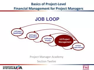
ISRM project • IPQs & IPDs Splice measurements
Various configurations in the machineExample of DFBAs in RIGHT sides: 8 m 50 m 90 m 130 m Courtesy of A. Jacquemod • Because of lack of voltage taps, we measure the average resistance over each interconnection • We do not measure magnet internal splices
Various configurations in the machineExample of DFBAs in LEFT sides: Courtesy of A. Jacquemod • Praying hand splices were identified as a potentially risky design
Various configurations in the machineExample of smaller DFBs: Courtesy of A. Jacquemod
Status on 12/07/2011: • Non counted: • + 4 D1 magnets (DFBXs) • We need 4 more technical stops to complete the whole machine (without DFBXs)! • 2 TS this year + 2 TS next year • Maybe less if we can do some tests during the next Christmas break?
Example of measurement on RQ10.R4 I have removed the inductive voltage during ramps!
Example of measurement on RQ10.R4 Error on the fit gives +/- 0.11 nW: Very good ! For a SAM we can achieve a resolution 10 times better R4 is very quite in term of noise compared to the rest of the machine
Example of measurement on RQ10.R4 Same scale as previous slide with RQ9.L8 measurements!
Measurements analyses: Point 2 and point 8 are very noisy as expected (closest points to SPS injection lines) Point 1L (but not 1R ???),
Measurements analyses: RQ10.R4 previous example RQ9.L8 previous example
Measurements analyses: For Q7 to Q10 magnets, most of the measurements were carried out at night! Exceptions are in L1, L2, Q10.R2, Q7, Q8 and Q9.R8 but not Q10.R8
Measurements analyses: Statistics: over 199 measurements
Conclusions • We have done so far 23 installation/removal of our 2x IRSM systems: It has to be done carefully but we can say that the method is well mastered! • It involves switching off HDSs, connecting/disconnecting instrumentation cables, resetting/power cycling QPS controllers and switching back on HDSs. • Also disconnecting/reconnecting the water cooled DC cables for hipotting of the circuit once the ISRM system is connected. • We have seen that we can measure IPDs, DFBLs, SAM without any problem. No showstoppers! • As foreseen, the RQ10 and RQ9 magnets are the most difficult magnets to measure because of long distances causing more noisy measurements, especially in point 1, 2 and 8. • It looks also that there is a correlation between noise level and time of measurements (ie. Measurements at night give better results). • Should we re-measure some positions? • Until now all splices measured seem to be correct.