ARC WELDING
ARC WELDING. INTRODUCTION. ELECTRIC ARC WELDING. The welding in which the electric arc is produced to give heat for the purpose of joining two surfaces is called electric arc welding. Principle.

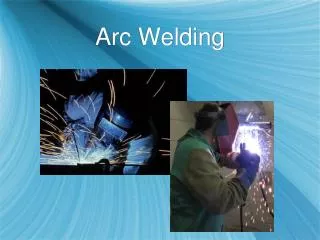
ARC WELDING
E N D
Presentation Transcript
ARC WELDING INTRODUCTION
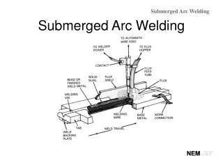
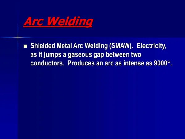
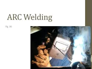
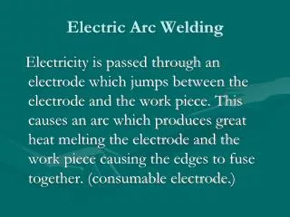
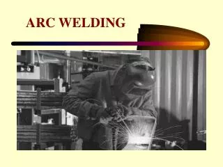
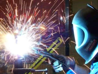
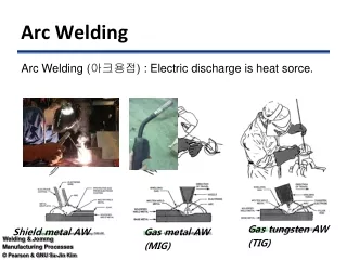
ELECTRIC ARC WELDING • The welding in which the electric arc is produced to give heat for the purpose of joining two surfaces is called electric arc welding
Principle • Power supply is given to electrode and the work. A suitable gap is kept between the work and electrode. • A high current is passed through the circuit. An arc is produced around the area to be welded. • The electric energy is converted into heat energy, producing a temperature of 3000°C to 4000°C. • This heat melts the edges to be welded and molten pool is formed. • On solidification the welding joint is obtained.
Electric Power for Welding • AC current or DC current can be used for arc welding. For most purposes, DC current is preferred. • In D.C. welding, a D.C. generator or a solid state rectifier is used. D.C. machines are made up to the capacity range of 600 amperes. • The voltage in open circuit is kept around 45 to 95 volts and in closed circuit it is kept 17 to 25 volts. D.C. current can be given in two ways (a) Straight polarity welding. (b) Reverse polarity welding.
Straight polarity welding. • In straight polarity welding work piece is made anode and the electrode is made cathode as shown in the fig. Electrons flow from cathode to anode, thus, heat is produced at the materials to be welded
Reverse polarity welding • In reverse polarity system the work is made cathode and the electrode is made anode. This welding is done specially for thin section
Effect of Arc Length • Arc length is the distance from the tip of the electrode to the bottom of the arc. It should vary from 3 to 4 mm. In short arc length, the time of contact will be shorter and will make a wide and shallow bead. The penetration is low as compared to long arc lengths.
Equipment used for Arc Welding • 1. D.C. Welding Equipment (a) AC Motor - Generator set (b) Diesel Engine - Generator set (c) Transformer - Rectifier welding set • 2. AC Equipment (a) Welding transformer set • 3. Equipment accessories (a) Leads (b) Holder (c) Connectors (d) Ground Clamps • 4. Operator’s tool (a) Chipping hammer (b) Wire brush (c) Arc shield (d) Closed shoe
AC Motor Generator: In this a generator is driven by a suitable AC motor. The average voltage of the generator is 25 volt. The current ranges from 25 to 100 amperes. The voltage in the generator is variable. The voltage can be set to the desired value with the help of rheostat. • Diesel Engine Generator Set: In this set, the drive is given by a diesel engine. Rest of the system is same as in case of A.C. motor generator. Diesel engine generator sets are used in the areas when electricity is not available. • Welding Transformer Set: It is used to step down the voltage supply. It consists of a primary and secondary circuit. The input is given to primary winding. By electromagnetic induction the current flows through the secondary coil. The output can be controlled as per requirement.
Cables or Leads: These leads are made up of copper or aluminium wire. The wires are insulated with rubber & cloth fiber. A heavy insulation is Necessary for these cables. • Face Shield: When arc is produced around the job, infrared rays and ultraviolet rays are produced. To protect the face and eyes from these dangerous rays, a shield is necessary. • Other Accessories & Tools:Other accessories & tools used for arc welding are shown in the fig
Welding Positions • In horizontal position it is very easy to weld. But many times it is impossible to weld the job in horizontal position. Other positions are classified as under: (a) Flat Position (b) Horizontal Position (c) Vertical Position (d) Overhead Position
Flat Position: • In flat positions the work piece is kept in nearly horizontal position. The surface to be worked is kept on upper side. The welding is done as illustrated in the fig
Horizontal Position • In this position, the work piece is kept as in the fig . Two surfaces rest one over the other with their flat faces in vertical plane. Welding is done from right side to left side. The axis of the weld is in a horizontal plane and its face in vertical plane
Vertical Position • In this position, the axis of the weld remains in approximate vertical plane. The welding is started at the bottom and proceeds towards top. Welding process is illustrated in figure.
Overhead Position • As shown in the figure, the work piece remains over the head of the welder. The work piece and the axis of the weld remain approximate in horizontal plane. It is the most difficult position of welding.
Types of Electrodes 1.Coated electrodes: Coated electrodes are generally applied in arc welding processes. A metallic core is coated with some suitable material. The material used for core is mild steel, nickel steel, chromium molybdenum steel, etc. One end of the coated core is kept bare for holding. 2. Bare electrodes: Bare electrodes produce the welding of poor quality. These are cheaper than coated electrodes. These are generally used in modern welding process like MIG welding.
Electrode Size • Electrodes are commonly made in lengths 250 mm, 300 mm, 350 mm, 450 mm, and the diameters are 1.6 mm, 2 mm, 2.5 mm, 3.2 mm, 4 mm, 7 mm, 8 mm and 9 mm.
Functions of Coatings • The coating on an electrode serves the following functions: 1. To prevent oxidation. 2. Forms slags with metal impurities. 3. It stabilizes the arc. 4. Increases deposition of molten metal. 5. Controls depth of penetration. 6. Controls the cooling rate.
TYPES OF JOINTS • Basic types of welding joints are classified as under: (a) Butt Joint In this type of joint, the edges are welded in the same plane with each other. V or U shape is given to the edges to make the joints strong. Some examples of butt joints are shown in the figure.
(b) lap joint • This type of joint is used in joining two overlapping plates so that the corner of each plate is joined with the surface of other plate. Common types of lap joints are single lap, double lap or offset lap joint. Single welded lap joint does not develop full strength as compared to double welded lap.
(c) T-Joint • When two surfaces are to be welded at right angles, the joint is called T-Joint. The angle between the surfaces is kept 90°
(d) Corner Joint • In this joint, the edges of two sheets are joined and their surfaces are kept at right angle to each other. Such joints are made in frames, steel boxes, etc.
(e) Edge Joint • In this joint two parallel plates are welded edge to edge.
( f ) Plug Joint • Plug joints are used in holes instead of rivets and bolts.