Download

1 / 13
130 likes | 311 Vues
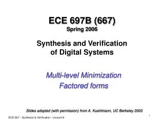
ECE 667 Spring 2013 Synthesis and Verification of Digital Systems. Technology Mapping for FPGAs. D.Chen, J.Cong, DAOMap : A Depth optimal Area Optimization mapping algorithm for FPGA Designs, ICCAD 2004. Programming bit P. F = x 1 ’x 2 ’ + x 1 x 2. 2-Input LUT. x1 x2 F

E N D
ECE 667Spring 2013Synthesis and Verificationof Digital Systems Technology Mapping for FPGAs D.Chen, J.Cong, DAOMap : A Depth optimal Area Optimization mapping algorithm for FPGA Designs, ICCAD 2004
Programming bit P F = x1’x2’ + x1x2 2-Input LUT x1 x2 F 0 0 1 0 1 0 1 0 0 1 1 1 0/1 F 0/1 0/1 0/1 x1 x2 FPGA Mapping (LUT-based) • How is it different from ASIC (standard cells) • Structural in nature, simpler • Any function with k inputs can be mapped into a k-LUT • Typically implemented by cut mapping • FPGA architecture: k-LUT ECE 667 Synthesis & Verificatioin - FPGA Mapping
f g d e h b a c FPGA Mapping - example A possible mapping onto 3-LUTs - each block has inputs ECE 667 Synthesis & Verificatioin - FPGA Mapping
Fv 3-feasible cone Cv Delay of 2 Definitions • DAG: Boolean network • Cone Cv: sub-network rooted on node v • K-feasible cone: |input(Cv)| K • Fanin Cone Fv: the largest Cv • k-feasible cut: a k-feasible Cv • Unit delay model: • Each LUT contributes one unit delay • Cut rooted on node C: cut with output C PIs a c b d e v ECE 667 Synthesis & Verificatioin - FPGA Mapping
Problem Formulation • Delay-optimal Area Optimization problem • Given: a Boolean network; an integer k (LUT size) • Goal: cover the network with k-feasible cones (k-LUTs), such that • Mapping depth (delay) is minimum • Area (number of LUTs) is minimized • NP-hard problem on area minimization • A two-step process • Cut enumeration + evaluation (delay, area) • Cut selection to minimize delay • Possible iteration to remap nodes on non-critical paths (area recovery) • Takes into consideration node duplication ECE 667 Synthesis & Verificatioin - FPGA Mapping
w z x y c a b Subcut d Subcut Another Subcut New cut Cut Enumeration w z x y c a b d • Process nodes in topological order from PIs to POs • Combine sub-cuts of the fanin nodes to create a new cut • If the size of the cut exceeds k (LUT size), discard the cut ECE 667 Synthesis & Verificatioin - FPGA Mapping
Delay = 1 Delay = 2 Delay = 1 Delay = 1 Delay = 3 Delay = 2 Delay = 2 Delay Propagation w z x y b Optimal Delay = 1 Optimal Delay = 1 a c Optimal Delay = 1 d e g f Optimal Delay = 2 • Delay computed using dynamic programming method. • The longest best delay on the POs is the optimal mapping delay ECE 667 Synthesis & Verificatioin - FPGA Mapping
As / 2 Area Estimation Tries to estimate area considering fanout effect AC = [Ai / f(i)] + UC i = input(C) • Ai : estimated area of the fanin cone of signal i • f(i) : fanout number of inputs • Uc : area of the cut itself • Can underestimate area due to node duplication Ap p m n o f(p) = 2 q r Cut C s X u t Cut Ct Cut Cu ECE 667 Synthesis & Verificatioin - FPGA Mapping
Duplication Cost Adjustment • Considers potential node duplications • Check the sub-cuts for multiple fanouts • Area adjusted by addition of duplication cost • Duplication Cost: • NCf : number of nodes contained by subcut Cf • IC : cutsize of C • fi : fanout number of subcut p m n o q r Subcut Cf2 NCf2 = 1 Subcut Cf1 s New cut C IC = 4 Multiple fanouts ECE 667 Synthesis & Verificatioin - FPGA Mapping
C3 fanin1 fanin2 Cost (Area) Function of a Cut Some Key parameters • IC: cutsize of C • NC: number of nodes covered by C • f(v): fanout number of the root node v • Pf: duplication cost a C1 c b C2 d e v ECE 667 Synthesis & Verificatioin - FPGA Mapping
Cut Selection • Once cuts are generated, traverse networks from POs to PIs and select cuts that map into LUTs • Select cuts such that timing is met and the area is minimized • Iterative Cut Selection Procedure • Local Cost Adjustment • Input Sharing • Slack Distribution • Cut Probing ECE 667 Synthesis & Verificatioin - FPGA Mapping
Local Cost Adjustment – Slack Distribution • SlackC = Reqv – 1 – MAX (Arri) i input(C) • If SlackC < 0, C is not a timing_feasible cut • The larger the SlackC, the better for C in terms of slack distribution effect w z x y b Largest arrival time among inputs a c C d Reqd : Required time of the root ECE 667 Synthesis & Verificatioin - FPGA Mapping
Algorithm Recap • Cut generationof k- feasible cuts • Area propagation under timing constraints • optimal area at a node is the minimum area among cuts that give minimum delay • Representation of the cost function for a cut more accurately • Global duplication cost adjustment • Cut selection involving local cost adjustment ECE 667 Synthesis & Verificatioin - FPGA Mapping