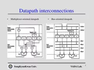
Computer Interconnections
Computer Interconnections. Week 2. OBJECTIVES. To discuss interconnections To explain the types of ISA buses To explore more advanced bus methodologies To describe arbitration techniques To explain PCI structures. Connecting.

Computer Interconnections
E N D
Presentation Transcript
Computer Interconnections Week 2
OBJECTIVES To discuss interconnections To explain the types of ISA buses To explore more advanced bus methodologies To describe arbitration techniques To explain PCI structures
Connecting • A computer consists of a set of components or modules of three basic types(up,mmry,I/O) that communicate with each other. • Different type of connection for different type of unit • Memory: consists of N words of equal length. Each word is assigned a unique numerical address (0,1,…,N-1). A word of data can be read from or written into memory. • Input/Output : refer to each of the interface to an external device as a port and give each a unique address (e.g.,0,1,…M-1). There are external data paths for the input and output of data external device and I/O module may be able to send interrupt signals. • Processor : reads an instructions and data, writes out data after processing, and uses control signals to control the overall system and also receives interrupt.
Memory Connection • Receives and sends data • Receives addresses (of locations) • Receives control signals • Read • Write • Timing
Input/Output Connection(1) • Similar to memory from computer’s viewpoint • Output • Receive data from computer • Send data to peripheral • Input • Receive data from peripheral • Send data to computer
Input/Output Connection(2) • Receive control signals from computer • Send control signals to peripherals • e.g. spin disk • Receive addresses from computer • e.g. port number to identify peripheral • Send interrupt signals (control)
CPU Connection • Reads instruction and data • Writes out data (after processing) • Sends control signals to other units • Receives (& acts on) interrupts
Buses • There are a number of possible interconnection systems • Single and multiple BUS structures are most common • e.g. Control/Address/Data bus (PC) • e.g. Unibus (DEC-PDP)
What is a Bus? • A communication pathway connecting two or more devices • Usually broadcast • Often grouped • A number of channels in one bus • e.g. 32 bit data bus is 32 separate single bit channels • Power lines may not be shown
Data Bus • Provide a path for moving data between system modules. • May consists of from 32 to hundreds of separate lines, number of lines refer to bus width and determines how many bits can be transferred at a time. • The width of the data bus is a key factor in determine overall performance. WHY?
Address bus • Identify the source or destination of data • e.g. CPU needs to read an instruction (data) from a given location in memory • Bus width determines maximum memory capacity of system • e.g. 8080 has 16 bit address bus giving 64k address space
Control Bus • Transmit both command and timing information between system modules. Timing signal indicate the validity of data and address information. Command signal specify operations to be performed. • Memory write: data on bus to be written into the adress location • Memory read: data from the addressed location to be placed on bus • I/O write: data on the bus to be output to the addressed I/O port • I/O read: data from the addressed I/O port to be placed on the bus • Transfer ACK: Indicate data has been accepted from or placed on the bus
Cont.. • Bus request: indicates that a module needs to gain control of the bus • Bus grant: indicates that a requesting module has been granted control of the bus • Interrupt request: indicates that an interrupt is pending • Interrupt ACK: Acknowledges that the pending interrupt has been recognized • Clock: used to synchronize operations • Reset: initializes all modules
Single Bus Problems • Lots of devices on one bus leads to: • Propagation delays • Long data paths mean that co-ordination of bus use can adversely affect performance • If aggregate data transfer approaches bus capacity • Most systems use multiple buses to overcome these problems
Bus Types • Dedicated • Separate data & address lines • Multiplexed • Shared lines • Address valid or data valid control line • Advantage - fewer lines • Disadvantages • More complex control • Ultimate performance
Bus Arbitration • More than one module controlling the bus • e.g. CPU and DMA controller • Only one module may control bus at one time • Arbitration may be centralised or distributed
Centralised or Distributed Arbitration • Centralised • Single hardware device controlling bus access • Bus Controller • Arbiter • May be part of CPU or separate • Distributed • Each module may claim the bus • Control logic on all modules
Timing • Co-ordination of events on bus • Synchronous • Events determined by clock signals • Control Bus includes clock line • A single 1-0 is a bus cycle • All devices can read clock line • Usually sync on leading edge • Usually a single cycle for an event
PCI Bus • Peripheral Component Interconnection. • Develop in 1990 for Pentium-based system and released all patents to the public domain. • PCI may be configured as a 32 or 64 bit • 49 mandatory signal lines.
PCI Bus Lines (required) • Systems lines : include the clock and reset pins • Address & Data : include 32 lines that are time multiplexed for address and data. The other lines in this group are used to interpret and validate the signal lines that carry the address and data. • Interface Control : control the timing of transactions and provide coordination among initiators and targets • Arbitration : these are not shared lines and each PCI master has its own pair of arbitration lines that connect it directly to the PCI bus arbiter. • Error lines : used to report parity and other error
PCI Bus Lines (Optional) • Interrupt pins : provide for PCI devices that must generate requests for service. Each PCI device has its own interrupt line or lines to an interrupt controller. • Cache support pin : these pins are needed to support a memory on PCI that can be cached in the processor or another device. • 64-bit bus extension pin : include 32 lines that are time multiplexed for address and data and that are combined with the mandatory address/data lines to form a 64-bit address/data bus. Other lines in this group are used to interpret and validate the signal lines that carry the address and data. There are two lines that enable two PCI devices to agree to use 64 bit capability. • JTAG/boundary scan pins : These signal lines support testing procedures define in IEEE stabdard 1149.1.
PCI Commands • Transaction between initiator (master) and target • Master claims bus • Determine type of transaction • e.g. I/O read/write • Address phase • One or more data phases