Network Layer Project: Packet Routing Using Socket Programming
This project involves designing and implementing a network layer solution that utilizes socket programming for both client and server applications across any platform. Your project must demonstrate the ability to route packets from a source to a destination while managing communication across varying network topologies. This is an individual or group project (up to three). The final proposal must be submitted on one page, detailing your approach and outlining the expected functionalities. The project is due at the end of the semester.


Network Layer Project: Packet Routing Using Socket Programming
E N D
Presentation Transcript
Network Projects • Must utilize sockets programming • Client and Server • Any platform • Please submit one page proposal • Can work individually or in groups of two or three. • Project will be due at the end of the semester.
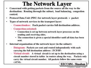
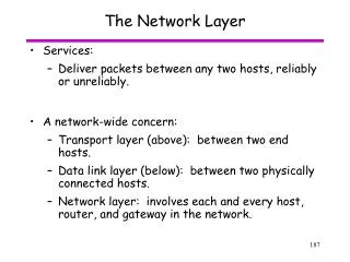
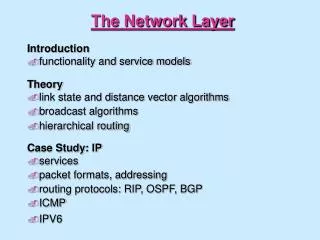
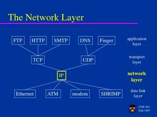
Network Layer • Route packets from source to destination • first layer that knows about communications beyond a single connection • must know the topology of the network • Interface between transport layer and to data link layer
Goals of the Network Layer* • The services should be independent of the subnet • The transport layer should be shielded from the number, type and topology of the subnets present • The network addresses made available to the transport layer should use a uniform numbering plan, even across LANs and WANs *Andrew S. Tanenbaum
Connection-oriented vs Connectionless Routing • Connectionless • Subnet is unreliable • Primitives • Send Packet • Receive Packet • Hosts reorder packets • Each packet must provide full destination address • Each independently routed packet is a datagram • IP is a connectionless protocol
Connection-oriented vs Connectionless Routing • Connection-oriented • All communication begins with the establishment of a connection. This connection is called a virtual circuit. • Identifiers are assigned to each connection • Packets arrive in order • Each packet must connection identifier • ATM is a connection-oriented protocol
Internet Protocol (IP) • IP is the network layer of the TCP/IP reference model
IP Packets (datagrams) • Network layer peers communicate via IP packets • Ip Packets consist of a header and a data area Datagram header Datagram data area
IP Datagrams are Encapsulated into Data Link Frames by the Data Link Layer Datagram header Datagram data area Frame Data Frame Header
Maximum Transfer Units (MTU) • Maximum frame size available • Ethernet (approximately 1500 bytes) • Minimum MTU is 576 • What happens if we can’t fit an entire datagram into a single frame? • Fragment the datagram so that it can be sent in multiple frames. • Fragmentation and reconstruction occur at the network level. • Reconstruction occurs at the final destination only.
IP Header Fields • IHL - Length of header in 32-bit words • normally 5 • Type of Service • Precedence (bits 0-2) • 8 levels of precedence • D - low delay (bit 3) • T - high throughput (bit 4) • R - high reliability (bit 5) • Total Length is in 8-bit bytes
IP Header Fields • Identification (16-bits) • Which datagram does this fragment belong to? • DF • Don’t Fragment (576 or less must be supported) • MF • More Fragments • All but the last fragment has this bit set • Fragment Offset • Where in the datagram does this fragment go? • Units are 8 bytes.
IP Header Fields • Time to Live (8-bits) • Counter that is decremented each time the datagram traverses a router. Datagram is deleted when Time to Live is zero. • Protocol (8-bits) • Transport protocol in use (e.g., TCP or UDP) • Header Checksum • Basic error detection mechanism • Recomputed at each hop (Time to Live changes) • Source and Destination IP address (32-bits each)
Network/Host Address Breakdown • Class A Networks • (N.H.H.H) • 126 networks with 16 million hosts each • Class B Networks • (N.N.H.H) • 16,382 networks with 64K hosts each • Class C Networks • (N.N.N.H) • 2 million networks with 254 hosts each
Subnets • Problem: • We are rapidly running out of IP addresses • Many networks do not have the maximum number of hosts that can be supported • Temporary Solution: • Create subnet works with smaller numbers of hosts. • Changes the distribution of network and host addresses • Uses some of the bits originally allocated for the host address for the network address
Basics of Internet Routing • Look at the destination IP address • Extract network address • If network is directly connected, send the datagram directly • If network is indirectly connected, lookup the address of the network in a routing table.
Routing on a LAN • Datagrams can be routed directly to a destination host that is connected to the same LAN • Ethernet cards all have a unique 6-byte address • The hosts maintain a table of IP to Ethernet address translations • This table is maintained automatically using ARP
Address Resolution Protocol (ARP) • The source broadcasts the destination address to the local network (along with the local source’s address) requesting the Ethernet address of the corresponding host • The destination host responds by sending its Ethernet address to the source host • The destination host sends the data to the destination and records the IP/Ethernet address pair for future use.