TCS Installation Update: Laser System Telecon Results at LLO, Jan. 8, 2014
130 likes | 210 Vues
Important updates from the TCS installation and results discussed during the Systems Telecon at LLO. Includes details on CO2 Laser Status, optics installation, alignment efforts, and calibration procedures.

TCS Installation Update: Laser System Telecon Results at LLO, Jan. 8, 2014
E N D
Presentation Transcript
TCS installation & results at LLO Update: Systems Telecon 8th Jan 2014 Aidan Brooks (for the TCS Team) G1400018-v1
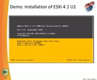
CO2 Laser Status • Enclosures installed • Lasers plumbed • Phase I (central heating) optics to be installed in January
HWS cartoonlayout • Hartmann in-air table • Next to HAM4 • Probe beams injected • Into main optical axis • Retro-reflected from ITMX and ITMY • Accumulated wavefront distortion is readout by HWS on return beam • In-vacuum optics in HAM4 • Must match in-vacuum and in-air optical axes
HWS installation In-air optics • All optics installed • In-air and in-vacuum optics aligned separately • In-air and in-vacuum axes mated • Took some effort • Currently out of alignment following December vent • Calibrated • HWS lever arm • Magnification In-vacuum optics
Injected HWS-X beamBS baffle is limiting aperture Earthquake stop HWS-X beam
Transmitted HWS-X beamMostly clean Earthquake stop shadow Edge of baffles Diffraction from dust on an optic
Stray reflections from in-vacuum optics • We see stray reflections from optics within HAM4 • These can be mostly spatially filtered out. • Example of unfiltered reflection is shown here • Possibly require tweaking alignment of in-vacuum optics at a later date • If determined that these introduce significant noise
HWS-Y background noise measurements • Shows background defocus over time • Equivalent Power Absorbed ~ 1.2mW • 0.3% of maximum expected • Fluctuation is correlated with temperature variation by HWS • Expect to be able to remove some of temperature fluctuations
Recall: Indirect Ring Heater measurementMeasured 1064nm beam size
Directly observed RH thermal lens • Step 1: Apply ring heater • Step 2: See thermal lens form at glacial speed • Still need to characterize this lens. Need to measure astigmatism. • http://youtu.be/GcoqCn8Ytds No data points outside ring Ring heater ITM HWS beam -105 mm 0mm +105mm X coordinate
HWS beam position on test mass • Located the center of the test mass • Relative to the center of the HWS beam • Used the ring heater thermal lens Ring heater ITM HWS beam
Appendix: HWS alignment • Located return beams by swinging SR3 • Identified 2 reflections from ITM and 2 from CP • Once correct beam is identified: • Misalign SR3 to return beam to HWS • Adjust HWS input periscope until no misalignment is required on SR3