Download
1 / 11
110 likes | 255 Vues
Second Peer Review for New MGI Valves for NSTX- U (Update on Valve Testing). R. Raman, et al. October 29, 2013. Valve & System Requirements. Empty most of the plenum in <2ms after valve is triggered Requires large orifice (limited by physical size limitations)

E N D
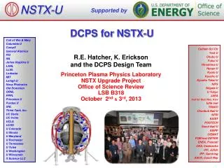
SecondPeer Review for New MGI Valves for NSTX-U(Update on Valve Testing) R. Raman, et al. October 29, 2013
Valve & System Requirements • Empty most of the plenum in <2ms after valve is triggered • Requires large orifice (limited by physical size limitations) • Rapid opening of the vacuum seal (coil voltage/current limits, PS size) • Compatible with external magnetic fields • Conventional solenoid valves not suitable • Compact in size so it can be installed on NSTX-U organ pipe flanges • High reliability • Few and simpler systems for operation • 4 – 5 identical systems needed for NSTX-U • Top & bottom organ pipe, 2 in mid-plane location (toroidally displaced) and one above mid-plane • Mid-plane valves need same diameter and length piping as organ pipe locations (one with length of tube ending at vessel & second in which the same length tube gets as close as reasonably possible to the plasma)
Horizontal view of valve on Organ Pipe(Original Installation Concept)
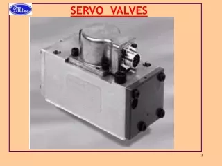
Electromagnetic Valve(similar in design to the ITER MGI valve) • Differential pressure across both plenums reduces load on pulsed power system • By properly balancing pressures, the power supply requirements are nearly independent of the pressure in the primary chamber • FY15: Max 5000 Torr (6.6 bar) • Consider >5000 Torr for FY16 and later • Requires upgrades to NSTX-U GIS
Valve Fabrication and Testing Update • Primary plenum operated to 3500 Torr • Secondary plenum at 2000 Torr • 850 V, 500µF, coil current 2.3kA, 400µs pulse (200µs, FWHM) • 100 Torr.L N2 injected • FY15 NSTX-U Experiments will use 50-100 Torr.L neon for poloidal comparison experiments (based on recent DIII-D experiments that used 60-90 Torr.Lneon)
Next Steps (1) • Move test set-up to a different room • Operate power system from an adjacent room, after adding door interlocks • Increase pressure to 5000 Torr in primary chamber • Increase charging voltage to the 1.5 to 2kV range • Collect fast baratron data of pressure pulse inside vessel • Finish Characterizing valve operating parameters for this first valve design (upto 1000 Torr.L)
TEXTOR Valve Operated at 2T Radial Fields (15 X NSTX-U valve)
Next Steps (2) • Test with magnets installed near the valve body • 6 inch x 3 inch x 1 inch magnets with surface field of ~1-1.3T (neodymium magnets to be used) • Higher forces can be simulated by increasing coil current above normal operating levels
Next Steps (3) & Modified Installation on NSTX-U (CASE 1) • Strengthen internal valve components • Possibly use 15-20 mm orifice size, dependent on Valve 1 results • Characterize this valve upto 1000 Torr.L • Describe results in Peer Review (Jan, 2014) – Then fabricate NSTX-U valves • Revised installation arrangement also avoids issue of lithium getting trapped near O-ring seals • Need to consider how to support current leads from the valve (2-5kA current, coax or twisted pair) • Additional support for external valve body • Valve will be electrically isolated from vessel by a suitable insulating (non-ceramic) spacer (0.5 inch thick), and insulated bolt sleeves