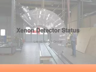
Xenon Detector Status
190 likes | 389 Vues
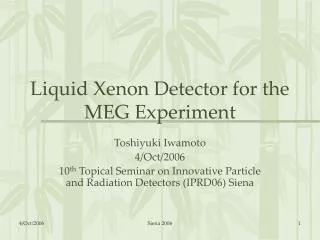
Xenon Detector Status. Liquid Xenon Group. Outline. Cryostat construction Honeycomb panel test at Pisa Assembly Cryogenic test at SIMIC Leak test at PSI Detector preparation at PSI Alignment at PiE5 PMT installation Schedule. Cryostat delivery to PSI. Delivery to PSI on 5/June

Xenon Detector Status
E N D
Presentation Transcript
Xenon Detector Status Liquid Xenon Group
Outline • Cryostat construction • Honeycomb panel test at Pisa • Assembly • Cryogenic test at SIMIC • Leak test at PSI • Detector preparation at PSI • Alignment at PiE5 • PMT installation • Schedule
Cryostat delivery to PSI • Delivery to PSI on 5/June • 6 weeks delay from the schedule reported in the previous review meeting • Delay of construction • not due to a technical problem • Delay of the cryogenic test at SIMIC • Difficulty to stop leak
Honeycomb panel test completed • 3rd panel delivered to Pisa at 16:30 on 20/Feb • Mounted on the text box and tested on 22, 23/Feb • 3 bar • Inspection by a Plyform expert • 4 bar x4 times • Hold for 3 minutes at 4 bar in the last test • Panel deformation (max) • 0.3 mm at 1 bar • 3.4 mm at 4 bar Holes for evacuation
Low temperature test • Wrapped with insulators and cooled with LN2 • Pressurized with compressed air • 2 bar • No damage on the panel found
And mounted on the cryostat • 400 micron carbon-fiber plate between the panel and window to fill the gap As of 13/Mar
Cold and Warm Vessel Assembly As of 19/April
Cryogenic Test at SIMIC • -18/May • All nuts on the covers of the cold vessel were fastened tightly and the warm vessel was evacuated whole weekend. • 21/May • He leak test. 1.8Bar He was filled and found that the leak rate was larger than 10-4 mbarl/sec. Keep evacuation during the night. • 22/May • cooling using cold gas from the LN2 tank. Cold gas in the cold vessel Most parts were cooled down to -5~-10 degree C. • 23/May • liquid N2 through the cooling pipe. All parts cooled below -110 degreeC around 12:00. • Then N2 gas at 1.0Bar and He gas filled step by step with measuring leak rate. • N2 1.0 bar He 0.2 bar 5x10⁻⁷ mbarl/sec • N2 1.0 bar He 0.4 bar 1.6x10⁻⁶mbarl/sec • N2 1.0 bar He 0.6 bar 7.8x10⁻⁶mbarl/sec • N2 1.0 bar He 0.8 bar 2.2x10⁻⁵mbarl/sec • The leak was not fixed at SIMIC by any means. • We decided to bring the cryostat to PSI and perform a leak test
Cryostat arrived at PSI • Delivery at 7:00 am on 5/June • Works to be done • Cleaning • Leak/pressure test • Alignment • PMT installation • …
Leak and Pressure Test at PSI • The metal gasket was not compressed correctly due to deformed shape of the flange • Re-machining the flanges by hand • Supporting structure installed to evacuate the inner vessel for the leak test cover flange gasket
Leak Test at PSI • Finally we found a hole on the welding line of the thin window!
Leak test again • After closing the hole, we performed a leak test again (with recycling the metal gaskets and with viton O-rings) • Cracks found at corners • Eddy-current measurement • US-bottom d1.3mm L7mm, -top OK • DS-bottom d0.8mm L13mm, -top d0.8mm L5mm • It was confirmed that these did not cause leak. • In the end we confirmed the tightness of the cryostat by using viton O-rings. • Leak rate < 3x10⁻⁹ mbarl/sec
Alignment at PiE5 • Decide the cryostat position on the platform. • Check how we can install the cryostat in the electronics hut
Alignment at PiE5 • Alignment of the cryostat • PMT support is aligned relative to the beam line within an accuracy of 1mm • Cryostat leg positions determined on the platform • Screw holes to fix the legs • G10 insulator between the platform and legs
Piping and cabling • Working in a clean hut • Cabling from patchpanels to feedthru almost finished • LN2, GXe, LXe piping is ongoing in parallel to PMT installation
PMT installation • Patchpanel – Feedthru cabring completed • PMT installation started on 8/July • Outer and Top PMT installation completed on 9/July • Now working on the inner (as of 12/July)
Schedule • PMT installation, -19/July • PMT test at room temperature, 20-23/July • He leak test, 25-28/July • Ready to move to PiE5 on 30/July • Evacuation and liquefaction in August • 950 liter xenon is already liquefied • Alpha/cosmic runs at the end of August • In parallel to purification • Monitor xenon purity