Liquid Xenon Detector
400 likes | 429 Vues
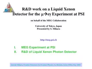
Liquid Xenon Detector. Xenon Detector Group. Contents. Cryostat Construction PMT Cryogenic/Gas System (Calibration Carlo’s presentation) Liquid H 2 Target and NaI Detector Slow Control Measurements of UV Light Reflection on Al and PEEK Schedule. Cryostat. Vessels Windows

Liquid Xenon Detector
E N D
Presentation Transcript
Liquid Xenon Detector Xenon Detector Group
Contents • Cryostat Construction • PMT • Cryogenic/Gas System • (Calibration Carlo’s presentation) • Liquid H2 Target and NaI Detector • Slow Control • Measurements of UV Light Reflection on Al and PEEK • Schedule
Cryostat Vessels Windows Status & Schedule
Cryostat Construction • The main construction activities: • The main flanges are assembled, welded and pre-machined. • All parts of the vessels are prepared and assembled. • The cold and warm vessel are leak tested using provisory covers. • The two vessels are machined, providing the necessary apertures. • The windows are welded on the body. • Leak and pressure tests are performed. • The phototube support structure is installed and adjusted. • The attachments to fix the structure are welded on the cold vessel. • Temperature sensors and heaters are installed. • The two vessels are assembled together. • The connection between them are done. Bellows are welded. • A leak test of those weld is done. • A cryogenic test is performed. • Another leak test after the cryogenic test is repeated. • The windows construction are done in parallel: • Prepare frames, steel sheet, honeycomb panel, and test box. • Welding of the parts. • Leak test of the welding • Installing the honeycomb panel • Pressure test with instrumentation is repeated. • Leak test after the pressure test. • The window are installed on the chamber. } Step 1 } Step 2 } Step 3 } Step 4 } Step 1 } Step 2 } Step 3
Construction Procedure Assemble and weld Leak test Machining Warm Pressure & Leak test Assemble and weld Assemble two vessels Weld Chimneys Leak & Cryogenic tests Install Windows Install sensor, PMT support attachment, etc. Assemble and weld Leak test Machining Cold Assemble and weld Pressure & Leak test Step 1 Step 2 Step 3 Step 4
Warm/Cold Vessels Dec/ 2005 Feb/ 2006 Apr/ 2006 Apr/ 2006
Leak Test before Machining • The cold and warm vessels were leak tested using provisory covers. • Cold vessel test 28-29-April-2006, Warm vessel 8-May-2006 • Some problems were found in the cold vessel • Excessive deformation were found during the test. • The provisory covers were only touching the flanges. Sealing plaster was used to make them vacuum tight. • An internal structure were added to control the deformation of the cold vessel. No Cover 1Bar Pressure Outer Vessel OK provisory Covers • Finite Element Analysis • Excessive deformation of the inner flange. • The real covers maintain the shape. • However we have a concern on the integrity of cold sealing, whether a local slip can occur between the cover and flange. With Cover 1Bar Pressure
3 Middle of June 4 2 Machining 1 • Cold Vessel • Cu cooling pipe will be welded on the back • Warm Vessel
Bellows/Chimneys • Pressure Test OK • Up to Dp=4Bar
Intermediate 5 mm frame weld Weld Weld Weld Intermediate 5 mm frame Windows • A thin foil is welded to a 5mm thick intermediate frame. • Backing with a honeycomb/carbon fiber panel for the cold window. Honeycomb/CF panel Cold Window Intermediate frame Honeycomb/CF panel Weld Weld Cross section A-A’ 0.4mmt window Al honeycomb CF Intermediate 5mm frame
Window Test Preparation Warm window test box • A 5 mm intermediate frame was welded to the test box. • After that the frame is cut out and welded to the vessel. • Preparation of test box. 14-May-2006 Cold Window Warm Window Pressure Pressure Cold window test box Honeycomb/CF panel Leak test
Warm Window Test • One warm window was tested: • Mechanically it was O.K. • However during the test leak was found • SIMIC realized that their construction proposal for windows was not feasible. They took three days to weld the foil to the 5 mm intermediate frame and 10 days to find leaks. After that the window was leaking during the test.
Cold Window Test • One cold window was tested: • Mechanically it was NOT O.K. Next slide • The welds were leaking. • SIMIC tried to repair the TIG weld using a brazing material, causing a disaster on the intermediate frame.
Carbon Fiber Transition area Al honeycomb Honeycomb/Carbon Fiber Panel Trouble • Mechanically the honeycomb/CF panel was NOT O.K. at Dp=3.7 bar. (Design value of the cryostat pressure tolerance is 3.0Bar) • The honeycomb/CF panel broke at one side. • FEA with sophisticated laminated elements OK • This buckling is attributed to local defects. OK on this side
Cold Vessel Warm Vessel weld Weld New Design of the Windows • New design proposed by SIMIC • The windows are welded directly on the bodies. • A leak test is performed on this weldon the body. • This design implies modification of the honeycomb… Honeycomb/CF panel Cold Vessel Weld Weld Warm Vessel Turn up the edges and weld along them
Previous design 5 plies of fiber sheets on each side of the panel +45/-45/0/-45/+45 Total thickness of 0.7 mm. Around the edge we use low modulus fiber sheets to make the bend (inter laminar method) and a filler material of epoxy with glass micro spheres (beads) inside. The honeycomb thickness is 19 mm and the density is 50 kg/m3. New design 8 piles of fibers Total thickness of 1.0mm A thicker honeycomb 24 mm with the same density (50kg/m3) to increase the inertia A fabric fiber with an intermediate modulus will be used to avoid the transition. Thus internal reinforcement will be made around the edges. New Honeycomb/CF Panel Design • How can we solve the problem on the Honeycomb/CF panel? • Change the material to avoid transition from the high modulus fiber to low modulus fiber around the edge and replace the filler material. • We are contacting Hexcel (http://www.hexcel.com) experts for advice.
Xenon Detector Platform Installation • Movable stage for the xenon detector • Operating position • “Parking” position • Mounting activity at PSI by Pisa group • started on 4/June and finished on 9/June • Tested successfully with 1.6+0.6 ton weights on it. 2 3 1
Necessary Operation • After the windows are welded on the two vessel, we need to do the following operation: • A leak test on the window welds • A pressure test closing all the aperture and covers. • After pressure tests of two vessels are done, we have to perform a leak test again. • The PMT support structure is installed and adjusted. The attachments are welded on the cold vessel. • A temperature sensors, heaters are installed. • The two vessels are assembled together. • The connection between them are done. Bellows are welded. • A leak test of those weld is done. • A cleaning and hand polishing is done on the cold vessel. • A cryogenic test is performed. • After the cryogenic a leak test is performed again.
Week 19-23 June: Warm vessel: Complete welding of all nozzle (3 days). Cold vessel: Complete welding of CF 100 flanges, braze the cooling tube (3 days) Welding test of the windows (2days) New foil fabrications (4 days). Define Honeycomb materials and geometry (2 days) delivery (15 days) Week 26-30 June: Test box preparation: warm window test box (1day); cold window test box (3days). Welding of warm window on the test box (2 days) + helium leak test (1day)+ mechanical test (1day). Machining of cold vessel (5 days). Week 3-7 July: Welding of cold window on the test box (2days)- helium lesk test (1day). New honeycomb delivered – mechanical test cold window (1day). Welding window on cold vessel (2days) Week 10-14 July: Test warm vessel (2days). Helium test of cold window (1day) Honeycomb mounting and cold test preparation (1day) Pressure test cold vessel, 4 bar, (1day) Week 17-21 July: Dry out cold vessel (1day)- helium leak test of metallic sealing on covers (1day). Mounting of the phototube supporting structure (2days) Welding of the L bracket to hold the arches (phototube supporting structure) (1day) Installation of super insulation and temperature sensors (1day) Week 24 -28 July: Alignment and vessel integration (3days) Bellows welding (3day) Week 31July - 4 Agust: Helium leak test on the welds (1day) Internal polishing (3days) Cleaning and dryout (2days) Week 7- 12 August: Preparation and installation of equipmnets for the cryocenic test (1day) Cryogenic test (4days) Week 14- 18 August: Helium leak test of cold vessel (2days) Prepartation of shipmenet (2days) Week 21- 26 August: Delivery to PSI Cryostat Construction Schedule
PMT Final Delivery Insertion to holders Room temperature test
Vacuum break t Chlorine HCl Silica Metal Tube Al PMT Final Delivery and Test Status • Newly delivered PMTs (~250) in 2006 • LP 4th PMT test • 100 new PMTs tested, finished on 17/Mar/2006 • Pisa test facility • Test of 102PMTs finished on 12/May/2006 • 50 more PMTs (delivered in June) will be tested. • Delivered PMTs (We need 846 PMTs in total) • 870 PMTs ordered and delivered • 107 PMTs returned and ~120 PMTs will be returned (t>0.3mm) to Hamamatsu • 264 PMTs delivered for replacement • Hamamatsu investigated further • 5 PMTs w/ large tilt but w/o any remaining chlorine • High temp/humidity test OK
PMT Installation 5 6 1 7 2 8 3 4 9
PMT Installation cont’d • Window slope measurement • Done for all PMTs • Installation status • Side : 40 (out of 48) holders ready. PMTs with large D(≥0.3mm) have been replaced. • Once installed, but later Hamamatsu provided replacements. • Outer : 18 (out of 22) holders ready • Inner : 18 (out of 24) holders ready • Top/bottom: not started yet • Inner holders are located in a vacuum chamber (LP cryostat) to remove humidity as much as possible before installation to the detector Inner, Outer, Top/Bottom Side
PMT test before installing into the detector • Signal check before installing into the detector • NIM HV module • Oscilloscope • Measurements • All cable connections are checked simultaneously • Current (mA) at 800V • Pedestal distribution
Assembly hut Air Filter
Eg 170o 175o q p0 Calibration Anti Counter • p-pp0n • p0(28MeV/c) g g • 54.9 MeV < E(g) < 82.9 MeV • Need Anti-Counter (NaI) at the opposite side • Movable to scan the acceptance • Timing counter (Pb+Scinti) in front of the NaI detector for timing calibration • Another interesting possibility • Abandon NaI detector in coincidence • Detect one g with the xenon detector • Convert another in a 0.1X0 converter close to the H2 target • Detect conversion and measure conversion point with a “special counter” • Measure e+ branch of the pair in the chambers • H2 target and NaI detector with a movable stage are essential. g up p0 down g target q Eg p0 Eg Requiring q>170o FWHM = 1.3 MeV Requiring q > 175o FWHM = 0.3 MeV
Liquid Hydrogen Target • Liquid Helium Cooling • Installed to the position through the insertion tube • Thin entrance window (100 micron Mylar)
Liquefaction Test • Several tests • Super-insulation • Material of LHe inlet • In the last test we liquefied some hydrogen • Terminated because of exhausting available helium
NaI Mover Construction • 3x3 NaI crystals • For covering the xenon detector acceptance • +/-30cm in z • +/-60o in f • and +/-30o in q • All motions are motor-driven and remotely controllable
Detector Preparation Status • 3x3 NaI crystals • Readout electronics • APD Hamamatsu S8664-55 • 2 on 1 crystal • BD voltage ~400V, 5mmx5mm • Pre-AMP GND GN-0261 • (Shaper) • Temperature monitor and control • PT100 • Peltier • Plastic scintillator (+Pb converter) with fine-mesh PMTs for timing calibration • Simulation • Just started
Slow Control • Xenon Detector System • Storage • pressure, valves • Gas purifier • valves, flow meter, pressure, pressure reducer control • 1000L dewar • valves, pressure, temperature, refrigerator control, LN2 flow, heater • Detector • Valves, pressure, temperature, surface level, strain gauge, refrigerator control, LN2 flow, heater • Liquid purifier • Valves, surface level, level control, LN2 flow • NaI mover • Motor control, position sensor
Scheme SCS Module 2 Gas Purifier SCS Module 1 Storage SCS Module 0 NaI Mover SCS Module 4 Detector liquid Purifier MSCB Ethernet Adapter SCS Module 3 1000L Dewer Network Xenon SC Backend PC Backend backup Main Slow Control Logging & Alarm Xenon LabView Interface Status History Display The backend PC handles signals between SCS modules
qref qinc Laser beam Measurements of UV light reflection on Al and PEEK • We asked spectroscopic LENS laboratory in Firenze to perform some measurements and to provide us experimental data about the properties of • PEEK (used in the inner holders) • Aluminium (used in the others) (we are very grateful to them for their kindness and helpfulness). Reference frame for the measurements: qinc = 300 qref =+300 qinc = 450 qref = 00 qinc = 600 qref =-300 • Results indicates • >10% reflection on Al • negligible on PEEK • Checking with LP data linc = 160 nm (UV light). Movable optical prism
Schedule • Cryostat delivery at the end of August • PMT assembly installation and cabling takes 35 days. • Detector setup (evacuation, liquefaction, purification…) takes 45 days • Detector can be ready in November • DAQ can be started when liquefaction finishes • p0 calibration at the end of 2006 run
Up-to-date Schedule • Now on Google Calendar (public) • http://www.google.com/calendar/embed?src=3ci8a2d11cqeogq7g99j5sssm8%40group.calendar.google.com