Download
1 / 22
230 likes | 507 Vues
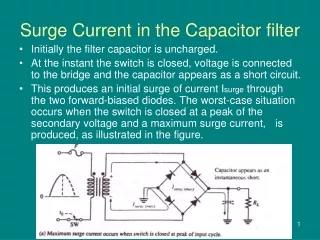
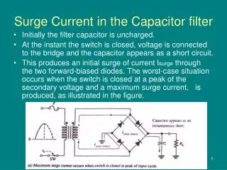
Surge Current in the Capacitor filter. Initially the filter capacitor is uncharged. At the instant the switch is closed, voltage is connected to the bridge and the capacitor appears as a short circuit.

E N D
Surge Current in the Capacitor filter • Initially the filter capacitor is uncharged. • At the instant the switch is closed, voltage is connected to the bridge and the capacitor appears as a short circuit. • This produces an initial surge of current Isurge through the two forward-biased diodes. The worst-case situation occurs when the switch is closed at a peak of the secondary voltage and a maximum surge current, is produced, as illustrated in the figure.
It is possible that the surge current could destroy the diodes, hence a surge-limiting resistor is sometimes connected, The value of this resistor must be small compared to RL. Also, the diodes must have a maximum forward surge current rating such that they can withstand the momentary surge of current. This rating is specified on diode data sheets as IFSM. The minimum surge resistor value can be calculated as follows :
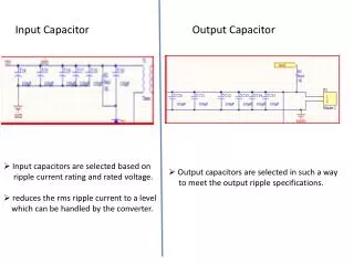
The LC Fitter • When an inductor is added to the filter additional reduction in the ripple voltage is achieved. The inductor has a high reactance at the 120 Hz ripple frequency, and the capacitive reactance is low compared to both XL and RL. The two reactances form an ac voltage divider that tends to significantly reduce the ripple voltage from that of a straight capacitor filter
Example • A 120 Hz full-wave rectified voltage with a peak value of 162 V is applied to the LC filter shown. Determine the filter output in terms of its dc value and the rms ripple voltage given that the rms ripple of an unfiltered full-wave rectified signal is calculated as Vr=0.308 Vp
Diode Clipper Circuits • These circuits clip off portions of signal voltages above or below certain limits, i.e. the circuits limit the range of the output signal. • Such a circuit may be used to protect the input of a CMOS logic gate against static. • Many examples can be found in transmitters and receivers in TV or radar or equipment control and protection circuits
There are two general categories of clippers: series and parallel. The series configuration is defined as one where the diode is in series with the load, while parallel variety has the diode in a branch parallel to the load • Series clippers:
Example Determine the output waveform for the network shown
Example • What would you expect to see displayed on an oscilloscope connected across RL
Biased Limiters • The positive limiter can be modified to limit the output voltage to the portion of the input voltage waveform above VBIAS - 0.7 V.
Similarly, the negative limiter can be modified to limit the output voltage to the portion of the input voltage waveform below - VBIAS + 0.7 V
Example • Determine the output voltage waveform (Assume non-ideal diodes)
Solution • When the voltage at point A reaches +7.7 V, diode D1 conducts and limits the waveform to +7.7 V Diode D2 does not conduct until the voltage reaches -5.7 V Therefore, positive voltages above +7.7 V and negative voltages below -5.7 V are clipped off.
Voltage-Divider Bias • In practice, the bias voltage sources that have been used to illustrate the basic operation of diode limiters can be replaced by a resistive voltage divider that derives the desired bias voltage from the dc supply voltage The bias resistors must be small compared to R1
Example • Describe the output voltage waveform for the diode limiter in figure
Solution The positive part of the output voltage waveform is limited to VBIAS + 0.7 V