Speed Control in DC Motors
230 likes | 1.21k Vues
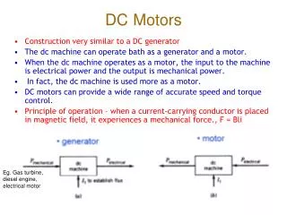
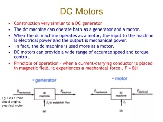
Speed Control in DC Motors. Shunt motor : Electromagnetic torque is T e = K a f d I a , and the conductor emf is E a =V t - R a I a . For armature voltage control: R a and I f are constant For field control: R a and V t are constant

Speed Control in DC Motors
E N D
Presentation Transcript
Shunt motor: Electromagnetic torque is Te=Ka fd Ia, and the conductor emf is Ea=Vt - RaIa. For armature voltage control: Ra and Ifare constant For field control: Ra and Vtare constant For armature resistance control: Vt and If are constant Speed Control in DC Motors
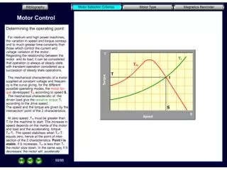
Speed Control in Shunt DC Motors Armature Voltage Control: Ra and Ifare kept constant and the armature terminal voltage is varied to change the motor speed. For constant load torque, such as applied by an elevator or hoist crane load, the speed will change linearly with Vt. In an actual application, when the speed is changed by varying the terminal voltage, the armature current is kept constant. This method can also be applied to series motor.
Speed Control in Shunt DC Motors Field Control: Ra and Vtare kept constant, field rheostat is varied to change the field current. For no-load condition, Te=0. So, no-load speed varies inversely with the field current. Speed control from zero to base speed is usually obtained by armature voltage control. Speed control beyond the base speed is obtained by decreasing the field current. If armature current is not to exceed its rated value (heating limit), speed control beyond the base speed is restricted to constant power, known as constant power application.
Speed Control in Shunt DC Motors Armature Resistance Control: Vt and Ifare kept constant at their rated value, armature resistance is varied. The value of Radj can be adjusted to obtain various speed such that the armature current Ia(hence torque, Te=KafdIa) remains constant. Armature resistance control is simple to implement. However, this method is less efficient because of loss in Radj. This resistance should also been designed to carry armature current. It is therefore more expensive than the rheostat used in the field control method.
Speed Control in Series DC Motors Armature Voltage Control: A variable dc voltage can be applied to a series motor to control its speed. A variable dc voltage can be obtained from a power electronic converter. Torque in a series motor can be expressed as
Speed Control in Series DC Motors Field Control: Control of field flux in a sries motor is achieved by using a diverter resistance. The developed torque can be expressed as.
Speed Control in Series DC Motors Armature Resistance Control: Torque in this case can be expressed as Rae is an external resistance connected in series with the armature. For a given supply voltage and a constant developed torque, the term (Ra+Rae+Rs+Kwm) should remain constant. Therefore, an increase in Rae must be accompanied by a corresponding decrease in wm.
DC Generator Arm. copper loss Ia2Ra+brush contact loss Input from prime-mover Arm. terminal power = Vta Ia Elec-magnetic Power =EaIa Output power = Vt IL Arm. copper loss Ia2Ra+brush contact loss Input power from mains =Vt IL Arm. terminal power = Vta Ia Elec-magnetic Power =EaIa Output available at the shaft DC Motor No-load rotational loss (friction +windage+core)+stray load loss Series field loss IL2Rs +shunt field loss If2Rf Series field loss IL2Rs +shunt field loss If2Rf No-load rotational loss (friction +windage+core)+stray load loss Power Division in DC Machines
Efficiency The losses are made up of rotational losses (3-15%), armature circuit copper losses (3-6%), and shunt field copper loss (1-5%). The voltage drop between the brush and commutator is 2V and the brush contact loss is therefore calculated as 2Ia.