Non-Ideal Characteristics
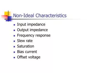
Non-Ideal Characteristics. Input impedance Output impedance Frequency response Slew rate Saturation Bias current Offset voltage. Input and Output Impedances. Ideal model assumes: R IN is infinite R OUT is zero In real life: R IN > 1 M W R OUT < 100 W. Input Impedance.

Non-Ideal Characteristics
E N D
Presentation Transcript
Non-Ideal Characteristics • Input impedance • Output impedance • Frequency response • Slew rate • Saturation • Bias current • Offset voltage
Input and Output Impedances • Ideal model assumes: • RIN is infinite • ROUT is zero • In real life: • RIN > 1 MW • ROUT < 100 W
Input Impedance • In either configuration, voltage across RIN will be small (ideally zero) if A0 is high. Current through RIN should, therefore, be small. • Effect will be more notable for non-inverting configuration where ideal input current is zero.
Output Impedance • To calculate output impedance: • Imagine the input voltage is zero. • The output voltage should also be zero. • The output looks like just ROUT connected to ground. • To calculate/measure ROUT, connect a signal generator to the output and calculate/measure the current.
Output Impedance • With the input set at zero, the equivalent circuits for non-inverting and inverting configurations are identical. • Actual output impedance is VOUT/I.
But, Calculating Actual Output Impedance
We know that A0 >> 1 and that ROUT is either small or comparable with R1 and R2. Typically, ROUT appears to be reduced by several orders of magnitude.
Input/Output Impedance Summary • Negative feedback is very good at compensating for non-ideal properties of the amplifier. • The effects of finite input impedance and non-zero output impedance are greatly reduced thanks to negative feedback. • Eg. Using a 741, an amplifier with a gain of 10 has ROUT of around 100W x 10/105 = 10 mW! • NB. Negative feedback will not work so well unless the open-loop gain of the op-amp is very large. • Reasonable at d.c. and low frequencies. • At higher frequencies…
Frequency Response • The open-loop gain of an op-amp features in the calculations for: • Voltage gain • Input impedance • Output impedance • We assumed it was very large (near infinite) • True at low frequencies • Not so at higher frequencies
First order approximation: Open-Loop Gain vs. Frequency
Effects of Frequency Response Ideally, gain = 10
Frequency Response (cont) Constant, K, depends on the op-amp. For a 741 it is around 2p´106. i.e. A first order low-pass filter, cut-off frequency of 100 kHz.
Gain-Bandwidth Product • Cut-off frequency multiplied by mid-band gain is always the same value. • This is the gain-bandwidth product (1 MHz in this case).
Frequency Response Summary • It is impossible to design an amplifier whose gain exceeds A0(f) at any frequency. • At high frequencies, gain is limited by A0 which typically rolls-off at 20dB-decade. • The cut-off frequency is • The intersection of the low and high frequency asymptotes • The –3dB point • The gain-bandwidth product divided by the mid-band gain
Slew Rate • There is a maximum rate of change associated with the output of an op-amp. The Slew Rate. • Typical value for a 741 is 0.5 V/ms.
Rate of change of the output voltage is: To avoid slew rate limiting: Effect of Slew Rate on a Sine Wave For a sine wave output voltage of amplitude, A, and frequency, f:
Full Power Bandwidth If the amplitude of the sine wave output is just below the saturation level, the maximum frequency that an undistorted SINE WAVE output can be obtained is often known as the full power bandwidth. E.g. 741 with saturation levels of ±13.5 V: NB. More about saturation next time…
Summary • Real op-amps deviate from the ideal model in many ways. • Negative feedback automatically compensates for many of these. • Most of the time, therefore, the ideal model works pretty well… • …except under extreme conditions. • NB. Saturation comes up next time as an introduction to comparators.