Mitigating Non-Ideal End Effects in Ramped Field Undulators with Advanced Corrector Schemes
This study addresses the non-ideal end effects in undulators due to finite permeability and differential saturation of end poles. We analyze how the end kick, influenced by the undulator field, can be managed using dipole correctors co-wound with the main coils. The paper discusses design strategies for odd-pole configurations, kick correctors, and their connection schemes to achieve effective control over entrance and exit kicks. The goal is to improve undulator performance while maintaining independent control of magnetic fields.

Mitigating Non-Ideal End Effects in Ramped Field Undulators with Advanced Corrector Schemes
E N D
Presentation Transcript
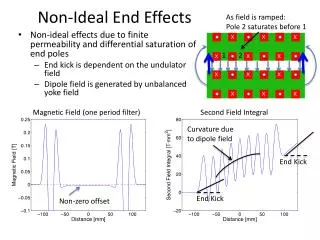
Non-Ideal End Effects As field is ramped: Pole 2 saturates before 1 1 2 • Non-ideal effects due to finite permeability and differential saturation of end poles • End kick is dependent on the undulator field • Dipole field is generated by unbalanced yoke field Magnetic Field (one period filter) Second Field Integral Curvature due to dipole field End Kick x x x x x x End Kick Non-zero offset x x x x x x
End Design and Correction Scheme • Odd number of poles • Ideal end design is used for the main coil (1/8, 1/2, 7/8) • Kick corrector + field clamps placed at each end (only generates a kick) • Dipole corrector is co-wound with the main coil in the first pocket (generates both kick and dipole) • Strength of both correctors is varied as a function of the undulator field (look-up table) Second Field Integral Kick Corrector After Correction
Lead Configuration • Main current leads at each end with a return line on the back of the undulator (< 1000 A) • Dipole correctors (co-wound in the first pocket) wired in series (< 20 A) • In principle the kick correctors could be wired in series, but we want independent control of the entrance and exit kicks (2 × < 100 A) Entrance Kick Corrector (<100 A) Exit Kick Corrector (<100 A) Lead in Lead out Main Leads (< 1000 A) and Dipole Correctors ( <20 A) Lead in Lead out Dipole correctors Lead out Lead in Lead in Lead out Main Current return Lead in Lead out