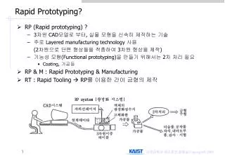
Rapid Prototyping
Rapid Prototyping. DTM Sinterstation 2500 plus, http://www.dtm-corp.com/products/sinterstation.html. Rapid Prototyping. What is Rapid Prototyping? A CAD technique to allow “Automatic” creation of a physical model or prototype from a 3-D model. Create a 3-D ‘Photocopy’ of a part.

Rapid Prototyping
E N D
Presentation Transcript
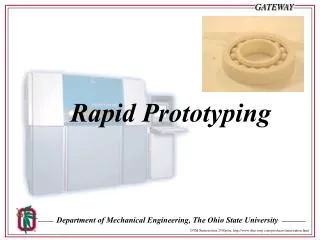
Rapid Prototyping DTM Sinterstation 2500plus, http://www.dtm-corp.com/products/sinterstation.html
Rapid Prototyping • What is Rapid Prototyping? • A CAD technique to allow “Automatic” creation of a physical model or prototype from a 3-D model. • Create a 3-D ‘Photocopy’ of a part. • Computer Real life • Why use Rapid Prototyping? • Decreases lead time • Facilitates concurrent engineering • Allows visualization of more ideas
Design Process Overview Concept Drawings Pre-lim Design Iterate Analysis Testing Physical Prototype Manufacturing
Prototype Classifications • Conceptual • Team members are aware of what is to be designed. • Physical (true prototype) • Form- Design verification, marketing and communication tool • High dimensional accuracy is NOT required • Non-technical people see how product looks and feels • Fit- Verify manufacturability, assembly, and fit • Required shape along with good dimensional tolerances • Material choice is not important • Function- Used to test functionality of real part • Material should be similar to actual part • Function prototype should have same failure modes and levels as actual part
Traditional Prototyping - Steps • Engineering Drawings • Machine or prototype shop to produce part • Part usually machined (Lathe, Mill etc.) • Problems: • Material incompatibility • Shop specialization (Can’t perform task you need) • Design limited by prototype tools available • Part too complex to produce (curved surfaces are very difficult) • Machine deficiencies (You have 3 axis mill, you need 5 axes) • Costs of traditional prototyping • Skilled Craftsman ($60-70/Hour shop time) • Time to receive model from shop • Time to get model into the public domain
Numerical Control Machining • Process: • Starts with solid model from some CAD package • (Solid Edge, Solid Works, I-DEAS or Pro-E for example) • Next create the desired tool paths • Advantages of NC over traditional machining • Significantly reduces time required for prototype fabrication • Identical parts created from one source code • Faster feed rates then a human could handle • Store the code conveniently (floppy or in NC machine itself) • Problems/Limitations: • Process not totally automatic. Operator must make many decisions: • Appropriate tools • How to fixture the stock • Re-fixturing during machining
NC - Brief History • Early 1800’s - first programmable machine created • Weaving machine controlled by holes punched in metal cards. • Machine can now read a code and follow a specified path • Late 1950’s - MIT developed a common language to describe cutting motions with a certain machine. • Code placed on a paper tape the machine could read
NC - in Present Day • Machining Centers • In prototyping many tools required by the user to create the parts. • Machining centers hold & manage a large number (up to 120) of tools • Eliminates tool-change time by machine operator • Much more complex parts with less operator interaction • Ex: T500 (Cincinnati Milacron) • NC software • Early program languages for NC required the path to be explicitly defined (Exact path known - no modification allowed -program began with the user entering the tool paths, NOT the workpiece shapes as is desired) • Programs now perform calculations for the user • Very complicated geometries easily handled by computer
NC Machining & Rapid Prototyping • NC machining requires a skilled operator to set up machine and to specify tools, speeds, and raw materials. • For this reason, many do not consider NC machining to be a true Rapid Prototyping (RP) technique. True RP should create a part from some model without any assistance. • NC Machining does have some benefits over “true” RP • NC Machining allows a wide range of materials for prototypes (true RP techniques often prohibit material for function prototype) • NC Machining allows better accuracy than most “true” rapid prototyping techniques (may be needed for fit prototypes) • True RP techniques can produce a prototype of a part that is impossible to manufacture. NC machining often reveals manufacturing limits in a given design.
Solid Freeform Manufacturing Many restrict true Rapid Prototyping to the Solid Freeform Manufacturing (SFM) procedures (i.e. RP=SFM) All the SFM procedures are based on some layering operation The CAD/CAM program takes the shape and models it as a series of thin layers stacked upon one another The SFM process then forms the part a layer at a time, starting at the bottom and working toward the top This can cause trouble with large overhangs-- one must somehow support the overhang in order to form the next layer Support must be used to form next layer Overhang
Solid Liquid Liquid Polymerization Melting & Solidification Powder Bulk Shape Melting Fused Deposition Modeling Ballistic Particle Manufacturing 1 Component Selective Laser Sintering Gluing Sheets Laminated Object Manufacturing Light Heat Thermal Polymer- ization Component & Binder 3D Printing & Gluing Two frequencies Beam Inter- ference solid One frequency Polymerization Foil Polymerization Solid Base Curing Photosolid. Layer at a Time Lamps Lasers Stereolithography SFM Layer Formation Methods
SFM Technology • Stereo-lithography- photopolymer cured by laser • Photosolidification Layer at a Time- photopolymer cured by light • Solid Base Curing- photopolymer is cured by UV light • Fused Deposition Modeling - molten plastic is extruded & solidifies • Ballistic Particle Manufacturing- microparticles of molten plastic • 3D Printing Direct Shell Production Casting- powder w/ binder • Selective Laser Sintering- fusible powder, fused by laser • Laminated Object Manufacturing- glued layers of sheets
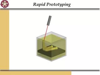
Stereolithography Stereo Lithography (SLA) was the first commercially available Solid Freeform Manufacturing system. It is still the industry leader, setting many industry trends. 1) Laser traces current cross section onto surface of photocurable liquid acrylate resin 2) Polymer solidifies when struck by the laser’s intense UV light 3) Elevator lowers hardened cross section below liquid surface 4) Laser prints the next cross section directly on top of previous 5) After entire 3-d part is formed it is post-cured (UV light) Note: care must be taken to support any overhangs The SLA modeler uses a photopolymer, which has very low viscosity until exposed to UV light. Unfortunately this photopolymer is toxic. Warpage occurs.
Stereolithography 3D Systems SLA 3500 Ref: http://www.3dsystems.com/index_nav.asp?nav=products&content=products/index.asp
Stereolithography Overview Laser is focused/shaped through optics. A computer controlled mirror directs laser to appropriate spot on photopolymer surface. Polymer solidifies wherever laser hits it. When cross section is complete, elevator indexes to prepare for next layer.
SLA Interface • Stereolithograpy was first commercial Solid Freeform Manufacturing process, released in 80’s by 3-D Systems • 3-D Systems developed interface between CAD systems and their machine • STL files (*.stl) allow CAD systems to interface with 3-D system machines • Virtually all subsequent SFM processes can use this same format (SFM industry standard) • Many CAD programs now can export the *.stl file for easy conversion from CAD to part
STL Files (*.stl) • STL files were based on a program called Silverscreen CAD • Silverscreen CAD represent boundary with all surfaces being approximated by polygons or groups of polygons • *.stl files use triangles or groups of triangles to approximate surfaces • Accuracy depends on the triangle sizes • Triangles assigned normal vectors for outward surface normal • Parts are defined by representing all their bounding surfaces as • faceted surfaces, using the triangular patches
Example of *.stl Representation Representing a sphere
Processing of *.stl Files • After the CAD system has generated *.stl file, it can be passed • to the SLA machine (or any SFM machine) • Machine then processes the *.stl file, slicing it into many thin • layers stacked on one another. The resulting files are called • slice files. • The shapes of the slices represent cross sections • In SLA (and in many SFM processes) thick solid sections of • material are often removed and replaced with cross hatching • Thus SLA (& many SFM) parts are usually hollow, with cross • hatching on the inside to add strength/stability
Photosolidification Layer at a Time 1) Cross section shape is “printed” onto a glass mask 2) Glass mask is positioned above photopolymer tank 3) Another rigid glass plate constrains liquid photopolymer from above 4) UV lamp shines through mask onto photopolymer- light only can pass through clear part, polymer solidifies there, polymer in masked areas remains liquid 5) Due to contact with glass plate, the cross linking capabilities of the photopolymer are preserved- bonds better w/ next layer 6) New coat of photopolymer is applied 7) New mask is generated and positioned, and process repeats 8) 12-15 minute postcure is required Much less warpage than SLA, but still uses photopolymers which are toxic.
Layer at a Time Solidification Mask is then placed under an ultraviolet lamp A glass mask is generated Laser then shines through mask, solidifying the entire layer in one “shot.” More rapid layer formation, and thorough solidification.
Solid Base Curing 1) Cross section shape is “printed” onto a glass mask 2) Glass mask is positioned above photopolymer tank 3) UV lamp shines through mask onto photopolymer- light only can pass through clear part, polymer solidifies there, polymer in masked areas remains liquid 4) All excess polymer is removed- part is again hit with UV light 5) Melted wax is spread over workpiece, filling all spaces 6) Workpiece is precisely milled flat 7) Glass is erased and re-masked, workpiece is placed slightly below surface in photopolymer, process repeats 8) After fabricating part, wax is melted and removed. Accurate, no support or post cure needed, but expensive & toxic
Solid Base Curing Cycle Shine UV Lamp through mask to solidify photopolymer Generate glass mask Coat with photopolymer Remove excess polymer, and fill gaps with liquid wax. Chill to solidify wax. Mill wax & workpiece
Fused Deposition Modeling (FDM) 1) A spool of thin plastic filament feeds material to FDM head 2) Inside FDM, filament is melted by a resistance heater 3) The semiliquid thermoplastic is extruded through FDM head 4) Material is deposited in a thin layer on formation 5) Material solidifies, forming a laminate 6) Next layer is formed on previous- lamina fuse together FDM modelers typically use nylon or some wax. The material is non toxic and can be used anywhere, including offices. Machines can be equipped with second head to extrude a support structure (BASS breakaway support system).
FDM Layer Formation FDM generated cross section Notice that the FDM filament cannot cross itself, as this would cause a high spot in the given layer
Fused Deposition Machine Stratasys FDM 2000 http://www.stratasys.com/
Ballistic Particle Manufacturing (BPM) Employs a technology called Digital Microsynthesis 1) Molten plastic is fed to a piezoelectric jetting mechanism, similar to those on inkjet printers. 2) A multi-axis controlled NC system shoots tiny droplets of material onto the target, using the jetting mechanism. 3) Small droplets freeze upon contact with the surface, forming the surface particle by particle. Process allows use of virtually any thermoplastic (no health hazard) & offers the possibility of using material other than plastic.
3-D Printing Direct Shell Production Casting (DSPC) First creates a disposable mold which is used to cast actual part 1) Thin distribution of powder is spread over powder bed 2) Inkjet printheads deposit small droplets of binder 3) Upon contact, binder droplets join powder to form solid 4) Piston supporting powder bed lowers so that the next layer can be spread and joined 5) Process repeats until completion 6) The shell that has been created is fired 7) Shell is filled with molten metal 8) Metal solidifies & shell is broken away from part Process allows use of metal for parts. Uses alumina powder & silica binder for shell. 3-D printing can have other uses.
Selective Laser Sintering (SLS) 1) A cartridge feeding system deposits a thin layer of heat fusible powder into a workspace container 2) The layer of powder is heated to just below its melting point 3) Carbon-dioxide laser traces the cross section. Particles hit by laser are heated to sintering point and bond into a solid mass. 4) A new layer of material is deposited on top of previous layer 5) Process repeats SLS modelers use nylon/polycarbonate powders, which are health hazards (dangerous to breathe). SLS does not require external support of overhangs, as loose powder provides support for new layers. Improvements in SLS technology have expanded allowed materials to ABS, PVC, and metals encapsulated in plastic. Some powdered metals have been directly sintered.
Laminated Object Manufacturing (LOM) 1) Sheet of material is laminated onto existing stack-up 2) Laser perforates the outline of cross section into top sheet (cross section is NOT completely cut out- full sheet remains) 3) Edges of top sheet are trimmed to match rest of stack-up 4) Next layer is bonded and process repeats 5) When finished- have solid block with perforations separating the actual workpiece from “extra” material. Extra material must be removed & part is sanded. LOM modelers use paper w/ polyester adhesive. They pose no health hazards and can be set up in offices. Further they are comparatively inexpensive, and require no supports for any overhangs. Unfortunately, LOM modelers also require more post-processing work (removing part from block).
Shape Deposition Manufacturing (SDM) Newer technique developed at Stanford & Carnegie Mellon Is it a pure SFM process? 1) Deposition- material is added by plasma or laser based welding techniques 2) Filler material is deposited around part 2) Material is shaped using conventional CNC 3) Solid is stress relieved 4) Components can be embedded 5) Filler is removed to leave only finished part
Sample Part Made from SDM Material: Stainless Steel (308) Support Material: Copper Deposition Method: Microcasting Support Removal: Etching Size: 75 x 50 x 42 mm Average Tensile Strength: 670 MPa Number of Layers: 29 Layer Thickness: 1.0 - 1.7 mm
Expansion of SFM Techniques • Advances in SFM technology have greatly increased the number of allowable materials and reduced the cost • However many limitations still exist-- can be combined with traditional processes • 3-d Printing Direct Shell Production Casting • SFM process creates a mold- casting is traditional process • Similarly one can generate a part from SFM process and then use investment casting • Molds can also be made from SFM part by encasing in RTV RTV mold can make urethane or epoxy parts • Can also create SFM mold and then coat with metal (process called metal spraying) to get functional mold
Summary • Many different processes for Rapid Prototype • Machining • Stereo-lithography • Phostosolidification Layer at a Time • Solid Base Curing • Fused Deposition Modeling • Ballistic Particle Manufacturing • 3D Printing Direct Shell Production Casting • Selective Laser Sintering • Laminated Object Manufacturing
Credits • This module is intended as a supplement to design classes in mechanical engineering. It was developed at The Ohio State University under the NSF sponsored Gateway Coalition (grant EEC-9109794). Contributing members include: • Gary Kinzel …………………………………….. Project supervisor • Chris Hubert and Alan Bonifas ..……………... Primary authors • Phuong Pham and Matt Detrick ……….…….. Module revisions
Disclaimer This information is provided “as is” for general educational purposes; it can change over time and should be interpreted with regards to this particular circumstance. While much effort is made to provide complete information, Ohio State University and Gateway do not guarantee the accuracy and reliability of any information contained or displayed in the presentation. We disclaim any warranty, expressed or implied, including the warranties of fitness for a particular purpose. We do not assume any legal liability or responsibility for the accuracy, completeness, reliability, timeliness or usefulness of any information, or processes disclosed. Nor will Ohio State University or Gateway be held liable for any improper or incorrect use of the information described and/or contain herein and assumes no responsibility for anyone’s use of the information. Reference to any specific commercial product, process, or service by trade name, trademark, manufacture, or otherwise does not necessarily constitute or imply its endorsement.