Digital Image Processing: A Remote Sensing Perspective FW5560 Lecture 7 Radiometric Correction
Digital Image Processing: A Remote Sensing Perspective FW5560 Lecture 7 Radiometric Correction. Radiometric correction


Digital Image Processing: A Remote Sensing Perspective FW5560 Lecture 7 Radiometric Correction
E N D
Presentation Transcript
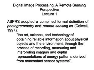
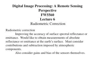
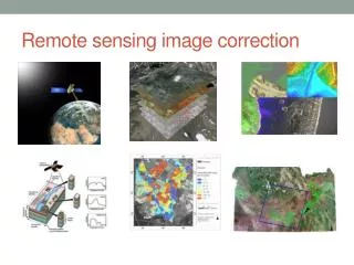
Digital Image Processing: A Remote Sensing PerspectiveFW5560Lecture 7Radiometric Correction Radiometric correction Improving the accuracy of surface spectral reflectance or emittance. Would like to obtain measurements of absolute reflectance or emittance at the earth’s surface. Must consider contributions and subtraction imposed by atmospheric components. Also consider gains and bias of the sensors themselves.
Relationship between DN and Spectral Radiance DN Slope = channel gain Intercept = channel offset RMIN RMAX L = spectral radiance (watts/cm2/sr) = spectral radiance of internal calibration lamps
Radiometric Correction Steps Output values for malfunctioning detectors are replaced by DNs of adjacent detectors in the same band Band responses to the calibration bands are use to characterize the in-orbit response functions of the individual channels. Functions are updated every 11,520 scan lines Histogram equalization procedure is performed Radiometric LUTs are calculated to convert the DNs to units of absolute radiance Used to measure difference in sscenrediance in a quantitative fashion within and between scense
Histogram equalization- minimize residual line to line striping DN frequency histogram for each sensor of each band, calculate the mean and std dev. Convert this numbers to absolute units using the original estimates of gain and offset. G’c,b = Gc.b (Sc,b/Sb) B’c,b = Bc,b + Gc.b(Mc,b – (SbMb/Sc,b)) Gc.band Bc,b= original estimates of gain and offset respectively Mc,b = mean associate the histogram for sensor c and band b in units of absolute radiance Sc,b= std dev. of the histogram Sb= avg of the standard deviations for a band
Atmospheric Correction Optical characteristics of the atmosphere are estimated either by using special features of the ground surface or by direct measurements of the atmospheric constituents or by using theoretical models. Various quantities related to the atmospheric correction can then be computed by the radiative transfer algorithms given the atmospheric optical properties. Second, the remotely sensed imagery can be corrected by inversion procedures that derive the surface reflectance.
ATCOR3 is atmospheric correction and haze removal software used to correct changes in the spectral reflectance of materials on the earth's surface. ATCOR3 can be integrated with a DEM for atmospheric correction in images of rugged terrain. Features: Produce sharp and brilliant satellite images Reduce the shadow effect in mountainous terrain Obtain better classification results by using real reflectance values Compare multi-temporal and multi-sensoral values Calculate value added products such as sky view factor and cast shadow calculation