Download
1 / 51
530 likes | 1.04k Vues
Illumination and Shading. Jian Huang, CS594, Fall 2001 This set of slides reference slides used at Ohio State for instruction by Prof. Machiraju and Prof. Han-Wei Shen. Illumination Vs. Shading.

E N D
Illumination and Shading Jian Huang, CS594, Fall 2001 This set of slides reference slides used at Ohio State for instruction by Prof. Machiraju and Prof. Han-Wei Shen.
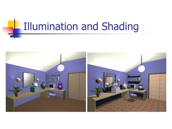
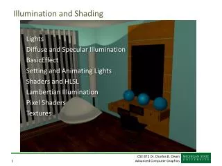
Illumination Vs. Shading • Illumination (lighting) model: determine the color of a surface point by simulating some light attributes. • Shading model: applies the illumination models at a set of points and colors the whole image.
Illumination (Lighting) Model • To model the interaction of light with surfaces to determine the final color & brightness of the surface • Global illumination • Local illumination
Global Illumination • Global Illumination models: take into account the interaction of light from all the surfaces in the scene. (will cover under the Radiosity section)
Local illumination • Only consider the light, the observer position, and the object material properties
Basic Illumination Model • Simple and fast method for calculating surface intensity at a given point • Lighting calculation are based on: • The background lighting conditions • The light source specification: color, position • Optical properties of surfaces: • Glossy OR matte • Opaque OR transparent (control refection and absorption)
Ambient light (background light) • The light that is the result from the light reflecting off other surfaces in the environment • A general level of brightness for a scene that is independent of the light positions or surface directions -> ambient light • Has no direction • Each light source has an ambient light contribution, Ia • For a given surface, we can specify how much ambient light the surface can reflect using an ambient reflection coefficient : Ka (0 < Ka < 1)
Ambient Light • So the amount of light that the surface reflect is therefore Iamb = Ka * Ia
Diffuse Light • The illumination that a surface receives from a light source and reflects equally in all directions • This type of reflection is called Lambertian Reflection (thus, Lambertian surfaces) • The brightness of the surface is indepenent of the observer position (since the light is reflected in all direction equally)
Lambert’s Law • How much light the surface receives from a light source depends on the angle between its angle and the vector from the surface point to the light (light vector) • Lambert’s law: the radiant energy ’Id’ from a small surface da for a given light source is: Id = IL * cos(q) IL : the intensity of the light source • is the angle between the surface normal (N) and light vector (L)
The Diffuse Component • Surface’s material property: assuming that the surface can reflect Kd (0<Kd<1), diffuse reflection coefficient) amount of diffuse light: Idiff = Kd * IL * cos(q) If N and L are normalized, cos(q) = N*L Idiff = Kd * IL * (N*L) • The total diffuse reflection = ambient + diffuse Idiff = Ka * Ia + Kd * IL * (N*L)
Examples Sphere diffusely lighted from various angles !
Specular Light • These are the bright spots on objects (such as polished metal, apple ...) • Light reflected from the surface unequally to all directions. • The result of near total reflection of the incident light in a concentrated region around the specular reflection angle
Phong’s Model for Specular • How much reflection light you can see depends on where you are
Phong Illumination Curves Specular exponents are much larger than 1; Values of 100 are not uncommon. : glossiness, rate of falloff
Specular Highlights • Shiny surfaces change appearance when viewpoint is changed • Specularities are caused by microscopically smooth surfaces. • A mirror is a perfect specular reflector
2N(N•L) N(N•L) L L L R = 2N(N•L) - L Project L onto N Double length of vector Subtract L f f f f f f Reflected Ray N L How to calculate R? R + L = 2(N*L) N R = 2(N*L) N - L R a V
Half Vector • An alternative way of computing phong lighting is: Is = ks * Is * (N*H)n • H (halfway vector): halfway between V and L: (V+L)/2 • Fuzzier highlight N L H V
Phong Illumination Moving Light Change n
Putting It All Together • Single Light (white light source)
Multiple Light Source • IL: light intensity • For multiple light sources • Repeat the diffuse and specular calculations for each light source • Add the components from all light sources • The ambient term contributes only once • The different reflectance coefficients can differ. • Simple “metal”: ks and kd share material color, • Simple plastic: ks is white • Remember, when cosine is negative lighting term is zero!
OpenGL Materials GLfloat white8[] = {.8, .8, .8, 1.}, white2 = {.2,.2,.2,1.},black={0.,0.,0.}; GLfloat mat_shininess[] = {50.}; /* Phong exponent */ glMaterialfv( GL_FRONT_AND_BACK, GL_AMBIENT, black); glMaterialfv( GL_FRONT_AND_BACK, GL_DIFFUSE, white8); glMaterialfv( GL_FRONT_AND_BACK, GL_SPECULAR, white2); glMaterialfv( GL_FRONT_AND_BACK, GL_SHININESS, mat_shininess);
OpenGL Lighting GLfloat white[] = {1., 1., 1., 1.}; GLfloat light0_position[] = {1., 1., 5., 0.}; /* directional light (w=0) */ glLightfv(GL_LIGHT0, GL_POSITION, light0_position); glLightfv(GL_LIGHT0, GL_DIFFUSE, white); glLightfv(GL_LIGHT0, GL_SPECULAR, white); glEnable(GL_LIGHT0); glEnable(GL_NORMALIZE); /* normalize normal vectors */ glLightModeli(GL_LIGHT_MODEL_TWO_SIDE, GL_TRUE);/* two-sided lighting*/ glEnable(GL_LIGHTING);
Shading Models for Polygons • Constant Shading (flat shading) • Compute illumination at any one point on the surface. Use face or one normal from a pair of edges. Good for far away light and viewer or if facets approximate surface well. • Per-Pixel Shading • Compute illumination at every point on the surface. • Interpolated Shading • Compute illumination at vertices and interpolate color
Constant Shading • Compute illumination only at one point on the surface • Okay to use if all of the following are true • The object is not a curved (smooth) surface (e.g. a polyhedron object) • The light source is very far away (so N.L does not change much across a polygon) • The eye is very far away (so V.R does not change much across a polygon) • The surface is quite small (close to pixel size)
Polygon Mesh Shading • Shading each polygonal facet individually will not generate an illusion of smooth curved surface • Reason: polygons will have different colors along the boundary, unfortunately, human perception helps to even accentuate the discontinuity: mach band effect
Mach Banding • Intensity change is exagerated • Dark facet looks darker and lighter looks even more lighter
Smooth Shading • Need to have per-vertex normals • Gouraud Shading • Interpolate color across triangles • Fast, supported by most of the graphics accelerator cards • Phong Shading • Interpolate normals across triangles • More accurate, but slow. Not widely supported by hardware
Gouraud Shading • Normals are computed at the polygon vertices • If we only have per-face normals, the normal at each vertex is the average of the normals of its adjacent faces • Intensity interpolation: linearly interpolate the pixel intensity (color) across a polygon surface
Linear Interpolation • Calculate the value of a point based on the distances to the point’s two neighbor points • If v1 and v2 are known, then x = b/(a+b) * v1 + a/(a+b) * v2
Linear Interpolation in a Triangle • To determine the intensity (color) of point P in the triangle, • we will do: • determine the intensity of 4 by linearly interpolating between 1 and 2 • determine the intensity of 5 by linearly interpolating between 2 and 3 • determine the intensity of P by linear interpolating between 4 and 5
Phong Shading Model • Gouraud shading does not properly handle specular highlights, specially when the n parameter is large (small highlight). • Reason: colors are interpolated. • Solution: (Phong Shading Model) • 1. Compute averaged normal at vertices. • 2. Interpolate normals along edges and scan-lines. (component by component) • 3. Compute per-pixel illumination.
Interpolated Shading - Problems • Polygonal silhouette – edge is always polygonal. Solution ? • Perspective distortion – interpolation is in screen space and hence for-shortening takes place. Solution ? • In both cases finer polygons can help !
Interpolated Shading - Problems • Orientation dependence - small rotations cause problems A B A C B D D C
Interpolated Shading - Problems • Problems at shared vertices – shared by right polygons and not by one on left and hence discontinuity • Incorrect Vertex normals – no variation in shade
Light Sources • Point light source • Directional light source: e.g. sun light • Spot light
Spot Light • To restrict a light’s effects to a limited area of the scene • Flap: confine the effects of the light to a designed range in x, y, and z world coordinate • Cone: restrict the effects of the light using a cone with a generating angle d
Light Source Attenuation • Takes into account the distance of the light from the surface I’L = I L * fatt (d) I’L: the received light after attenuation I L: the original light strength fatt: the attenuation factor d: the distance between the light source and the surface point • fatt = max ( 1/(c1 + c2*d + c3*d2) , 1) • C1, C2, C3 are user defined constants associated with each light source
More on Homogeneous Coordinates • To 4D: (x,y,z) -> (x,y,z,1) • Back to 3D: (x,y,z,w) -> (x/w, y/w, z/w) • A point is on a plane if the point satisfies 0 == A*x + B*y + C*z + D • Point P: (x,y,z,1). • Representing a plane N = (A,B,C,D). Point P is on the plane, if P dot N == 0
Transforming Normals • Transform P to P’ -> P’ = M * P (M is known) • and transform N to N’ -> N’ = Q * N • Let Q be our transformation matrix for N. • We want to make sure that after transformation, N’ is the normal of the transformed plane. That is, N’T * P’ = 0 • We get: N’T * P’ = (Q * N)T * (M * P) = NT * QT * M * P = 0