Download
1 / 49
490 likes | 614 Vues
This guide explores the fundamentals of illumination and shading in computer graphics. It discusses the importance of light sources and how they affect the appearance of objects, emphasizing the difference between local and global illumination. Key concepts like ambient, diffuse, and specular lighting are detailed, along with practical applications like OpenGL's lighting model. Users will learn about reflection, transmission, and how to achieve realistic three-dimensional visualizations by properly calculating the interaction of light with surfaces. Ideal for graphics enthusiasts and developers.

E N D
Illumination and Shading Mengxia Zhu Fall 2007 .
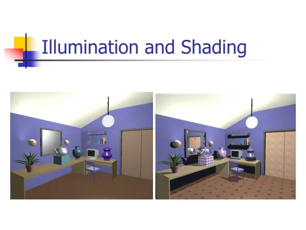
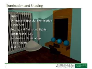
Why? • What light source is used and how the object response to the light makes difference • Lighting gives you a 3D view to an object • A unlit sphere looks no different from a 2D disk • To get realistic pictures, the color computation of pixels must include lighting calculations
Local and Global Illumination • Local illumination: a surface point receives light directly from all light sources in the scene. Consider in isolation • Global illumination: a point receives light after light rays interact with other objects in the scene. • Shadow • Refract through transparent object • Reflection and transmission rays
Illumination Vs. Shading • Illumination (lighting) model: To model the interaction of light with surfaces to determine the final color & brightness of the surface • Shading model: applies the illumination models at a set of points and colors the whole image.
Local illumination • Only consider the light, the observer position, and the object material properties V L
Types of Light • Ambient • Light that’s been scattered so much by the environment that its direction is impossible to determine - it seems to come from all directions • Diffuse • Light that comes from one direction, but it gets scattered equally in all directions • Specular • Light comes from a particular direction, and its tends to bounce off the surface in a preferred direction
OpenGL Lighting Model • OpenGL approximates lighting as if light can be broken into red, green, and blue components • The RGB values for lights mean different than for materials • For light, the numbers correspond to a percentage of full intensity for each color • For materials, the numbers correspond to the reflected proportions of those colors
Ambient light (background light) • The light that is the result from the light reflecting off other surfaces in the environment • A general level of brightness for a scene that is independent of the light positions or surface directions • Has no direction • Each light source has an ambient light contribution, Ia • For a given surface, we can specify how much ambient light the surface can reflect using an ambient reflection coefficient : Ka (0 < Ka < 1)
Ambient Light • Ambient, omni-directional light • So the amount of light that the surface reflect is therefore • Ka ambient coefficient Iamb =
Diffuse Light • The illumination that a surface receives from a light source and reflects equally in all directions • This type of reflection is called Lambertian reflection • The brightness of the surface is independent of the observer position (since the light is reflected in all direction equally) L
Lambert’s Law • Lambert’s law: the radiant energy for a given light source is: Id * cos(q) Id : the intensity of the light source • is the angle between the surface normal (N) and light vector (L) If N and L are normalized, cos(q) = • Surface’s material property: assuming that the surface can reflect Kd (0<Kd<1), diffuse reflection coefficient) amount of diffuse light.
The Diffuse Component • Brightness is inversely proportional to the area of the object illuminated (dot product of light vector and surface normal) • greatest when N and L are parallel • smallest when N and L are orthogonal • In calculations, max {N.L, 0} is used to avoid negative values • The total diffuse reflection = ambient + diffuse
Specular Light • These are the bright spots on objects (such as polished metal, apple ...) • Light reflected from the surface unequally to all directions.
Phong’s Model for Specular • Brightness depends on the angle between reflection vector (R) and viewer vector (V), i.e, on direction of viewer
Summing the Components Ambient + Diffuse + Specular = final
Phong Illumination Curves • Specular exponents are much larger than 1, and Values of 100 are not uncommon. • The specular reflection exponent n is 1 for a slightly glossy surface and infinity for a perfect mirror. : glossiness, rate of falloff
2N(N•L) N(N•L) L L L R = 2N(N•L) - L Project L onto N Double length of vector Subtract L f f f f f f Reflected Ray N L How to calculate R? R + L = 2(N*L) N R = 2(N*L) N - L R a V
N L H V Half Vector • An alternative way of computing phong lighting is: • H (halfway vector): halfway between V and L: (V+L)
Putting It All Together • Single Light:
Attenuation • Attenuation factor • Light attenuates with distance from the source • where d = distance between the light and object • kc = constant attenuation • A light source does not give an infinite amount of light • kl = linear term • kq = quadratic term • Models the theoretical attenuation from a point source • The intensity becomes
Spotlight Effect • When the vertex lies inside the cone of illumination produced by spotlight, its contribution to the light intensity is Where D gives the spotlight’s direction. The intensity is maximum in the center of cone and is attenuated toward the edge of the cone s is 1 if the source is not spotlight m is exponent determining the concentration of the light The intensity of light source is
Putting All Together Multiple lighting calculation in RGB mode gives Vertex color
Adding Lighting to the Scene • Define normal vectors for each vertex of each object • Create, select, and position one or more light sources • Create and select a lighting model • Define material properties for the objects in the scene
Creating Light Sources • Properties of light sources are color, position, and direction • void glLight{if}(GLenum light, GLenum pname, TYPE param); • void glLight{if}v(GLenum light, GLenum pname, TYPE *param); • Creates the light specified by light that can be GL_LIGHT0, GL_LIGHT1, … or GL_LIGHT7 • Pname specifies the characteristics of the light being set • Param indicates the values to which the pname characteristic is set • glEnable(GL_LIGHT0);
Color for a Light Source • GLfloat light_ambient[] = {0.0,0.0,0.0,1.0}; • GLfloat light_diffuse[] = {1.0,1.0,1.0,1.0}; • GLfloat light_specular[] = {1.0,1.0,1.0,1.0}; • glLightfv(GL_LIGHT0, GL_AMBIENT, light_ambient); • glLightfv(GL_LIGHT0, GL_DIFFUSE, light_diffuse); • glLightfv(GL_LIGHT0, GL_SPECULAR, light_specular);
Position of Light Source • Positional light source • (x, y, z) values specify the location of the light • GLfloat light_position[] = {x, y, z, w}; • glLightfv(GL_LIGHT0, GL_POSITION, light_position); • Directional light source • (x, y, z) values specify the direction of the light located at the infinity • No attenuation • GLfloat light_position[] = {x, y, z, 0}; • glLightfv(GL_LIGHT0, GL_POSITION, light_position);
Attenuation • Attenuation factor for a positional light • Needs to specify three coefficients • glLightf(GL_LIGHT0, GL_CONSTANT_ATTENUATION, 2.0); • glLightf(GL_LIGHT0, GL_LINEAR_ATTENUATION, 1.0); • glLightf(GL_LIGHT0, GL_QUADRATIC_ATTENUATION, 1.0); • Ambient, diffuse, and specular contributions are all attenuated
Spotlights • The shape of the light emitted is restricted to a cone • glLightf(GL_LIGHT0, GL_SPOT_CUTOFF, 45.0); • The cutoff parameter is set to 45 degrees • GLfloat spot_direction[] = {-1.0, -1.0, 0.0]; • glLightfv(GL_LIGHT0, GL_SPOT_DIRECTION, spot_direction); • specifies the spotlight’s direction which determines the axis of the cone of light • glLightf(GL_LIGHT0, GL_SPOT_EXPONENT, 2.0); • Controls how concentrated the light is
Multiple Lights • You can define up to eight light sources • Need to specify all the parameters defining the position and characteristics of the light • OpenGL performs calculations to determine how much light each vertex gets from each source • Increasing number of lights affects performance
Defining Material Properties • Specifying the ambient, diffuse, and specular colors, the shininess, and the color of any emitted light • void glMaterial{if}(GLenum face, GLenum pname, TYPE param); • void glMaterial{if}v(GLenum face, GLenum pname, TYPE *param); • Specifies a current material property for use in lighting calculations • Face can be GL_FRONT, GL_BACK, or GL_FRONT_AND_BACK • Pname identifies the particular material property being set • Param defines the desired values for that property
Reflectance • Diffuse and ambient reflection • Gives color • GLfloat mat_amb_diff[] = {0.1, 0.5,0.8,1.0}; • glMaterialfv(GL_FRONT_AND_BACK, GL_AMBIENT_AND_DIFFUSE, mat_amb_diff); • Specular reflection • Produces highlights • GLfloat mat_specular[] = {1.0,1.0,1.0,1.0); • Glfloat low_shininess[] = {5.0}; • glMaterialfv(GL_FRONT, GL_SPECULAR, mat_specular); • glMaterialfv(GL_FRONT, GL_SHININESS, low_shininess);
Shading Models for Polygons • Constant Shading (flat shading) • Compute illumination at any one point on the surface. Use face or one normal from a pair of edges. Good for far away light and viewer or if facets approximate surface well. • Per-Pixel Shading • Compute illumination at every point on the surface. • Interpolated Shading • Compute illumination at vertices and interpolate color
Constant Shading • Compute illumination only at one point on the surface • Okay to use if all of the following are true • The object is not a curved (smooth) surface (e.g. a polyhedron object) • The light source is very far away (so N.L does not change much across a polygon) • The eye is very far away (so V.R does not change much across a polygon) • The surface is quite small (close to pixel size)
Polygon Mesh Shading • Shading each polygonal facet individually will not generate an illusion of smooth curved surface • Reason: polygons will have different colors along the boundary, unfortunately, human perception helps to even accentuate the discontinuity: mach band effect
Smooth Shading • Need to have per-vertex normals • Gouraud Shading • Interpolate color across triangles • Fast, supported by most of the graphics accelerator cards • Phong Shading • Interpolate normals across triangles • More accurate, but slow. Not widely supported by hardware
Gouraud Shading • Normals are computed at the polygon vertices • If we only have per-face normals, the normal at each vertex is the average of the normals of its adjacent faces • Intensity interpolation: linearly interpolate the pixel intensity (color) across a polygon surface
Linear Interpolation • Calculate the value of a point based on the distances to the point’s two neighbor points • If v1 and v2 are known, then x = b/(a+b) * v1 + a/(a+b) * v2
Linear Interpolation in a Triangle • To determine the intensity (color) of point P in the triangle, • we will do: • determine the intensity of 4 by linearly interpolating between 1 and 2 • determine the intensity of 5 by linearly interpolating between 2 and 3 • determine the intensity of P by linear interpolating between 4 and 5
Phong Shading Model • Gouraud shading does not properly handle specular highlights, specially when the n parameter is large (small highlight). • Reason: colors are interpolated. • Solution: (Phong Shading Model) • 1. Compute averaged normal at vertices. • 2. Interpolate normals along edges and scan-lines. (component by component) • 3. Compute per-pixel illumination.
References • Slides from Karki at LSU • Jian Huang at UTK