ROUGH RUNWAY ANALYSIS Aircraft Dynamic Response
ROUGH RUNWAY ANALYSIS Aircraft Dynamic Response. Jack Hagelin Boeing Technical Fellow ASTM E-17 Seminar December 5, 2006. Types of Runway Roughness Impact on Aircraft. Three Types of Runway Roughness Impact on Aircraft: Limit Loads – Single Discrete Bump Events


ROUGH RUNWAY ANALYSIS Aircraft Dynamic Response
E N D
Presentation Transcript
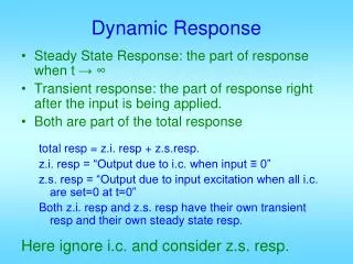
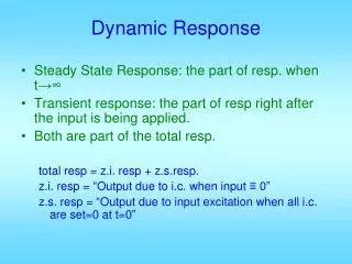
ROUGH RUNWAY ANALYSIS Aircraft Dynamic Response Jack Hagelin Boeing Technical Fellow ASTM E-17 Seminar December 5, 2006
Types of Runway Roughness Impact on Aircraft • Three Types of Runway Roughness Impact on Aircraft: • Limit Loads – Single Discrete Bump Events • Fatigue Loads – Continuous Long Wavelength Bumps • Truck Pivot Joint – Continuous Short Wavelength Bumps • Each type imposes a different runway roughness criteria. • Current standards address mainly first two types. • Third type is not directly addressed in current standards.
Limit Load Dynamic Taxi Analysis • Limit Load Critical Conditions • Constant speed taxi • Accelerated Takeoff • Decelerated Landing Rollout • Ride Comfort • Runway profile used as direct input • Goal is to use roughest runway reasonably expected in normal operation (FAR 25.235). • In absence of other data, AC 25.491-1 provides SF28R profile data. • Analyze both forward and reverse directions, and multiple tracks if available. • Discrete bump conditions also analyzed (Boeing single bump and FAR double bumps) • Runway crown effect for airplanes with more than two main gears • Important input parameters: • Airplane weight, cg, pitch inertia, speed, aerodynamic forces, and thrust • Landing gear location (wheelbase), number of gears, shock strut air curve, tire stiffness, brake force • Tail aerodynamic force affects nose gear load • Airplane on-the-ground natural frequencies (usually from 0.5 to 1.5 Hz) • Important output parameters: • Landing gear vertical loads, airplane cg acceleration, forward fuselage, and engine loads
Bump Height vs. Length DiagramFAA Certification Runway (AC 25.491-1) – SFO 28R 3 2 1
Limit Load Dynamic Taxi AnalysisResults – San Francisco (SFO) Runway 28R
Bump Height vs. Length DiagramSample Recently Measured CIS Rough Runway
Sample Rough Runway 200m section with critical bump Smooth line is curve fit used to flatten profile
3D Power Spectral Density (PSD) Plot Sample CIS Rough Runway Airplane Speed of 60 knots 1 2 3
Bump Height vs. Length DiagramsRussian Certification Runways (A, B, C, D)
1 2 3 3D PSD DiagramsRussian Certification Runways (A, B, C, D)
Limit Load Dynamic Taxi AnalysisCG Vertical Acceleration Comparison Limit Load Factor = 1.7g per AC 25.491-1
Fatigue Dynamic Analysis • Fatigue Critical Conditions • Preflight taxi • Takeoff roll • Landing rollout • Post-flight taxi • Runway profile used as direct input • ‘Typical’ runway/taxiway profiles used to match in-service statistical data • Important input parameters: • Airplane weight, cg, pitch inertia, speed, aerodynamic forces, and thrust • Landing gear wheelbase, number of gears, shock strut air curve, tire stiffness • Airplane on-the-ground natural frequencies (usually from 0.5 to 1.5 Hz) • Important output parameters: • Landing gear vertical loads • Airplane cg acceleration • Engine loads • Fuselage, wing, and horizontal tail incremental loads
Sample Taxiway which may be rough for Fatigue Critical Taxi Speed = 24 knots for 1 Hz airplane response
Main Gear Pivot Joint Analysis • Current runway standards do not adequately address this issue • On rough runways, the bogie pitch mode exhibits low damped resonant response at 10 to 20 Hz range due to short wavelength roughness (~2 to 7 m) • Important parameters for pivot joint analysis: • Pivot pin diameter • Friction coefficient in joint • Bearing pressure due to post load • Bearing surface velocity • PV (Pressure * Velocity) • Heat energy generated in the joint • Time duration of heating
F = Post Load F / 2 Inner Cylinder F / 2 R Bogie Pivot Joint F / 2 F / 2 Bogie Beam FF FA Pivot Joint Heat Calculations Pressure-Velocity = Friction Energy = Pivot Pin m = friction coefficient at bushing surface
Short Wavelength Runway Profile AnalysisPower Spectral Density (Overall Runway) • Shows bump height intensity versus bump wavelength Acceptable Threshold
Runway Profile Analysis3D Relative Power Spectral Density Acceptable 1500m Relative Runway Height PSD (dB) Runway Distance (m) Rough 2 7 Bump Wavelength (m)
Pivot Joint Dynamic Takeoff AnalysisResults – Typical International Runway
Pivot Joint Dynamic Takeoff AnalysisResults – Borderline Runway
Dynamic Analysis Results –Takeoff RollPivot Joint Heat per Unit Bearing Area (Normalized) vs. Runway
Dynamic AnalysisCG Vertical Load Factor vs. Pivot Joint Heat Correlation of CG Acceleration with Pivot Joint Heat is not strong. (Due to widely different response frequencies)
Summary • Three types of airplane response to runway roughness require three different acceptance criteria. • Airplane dynamic analysis is necessary to evaluate effects of rough runways on aircraft design, however, runway profile analysis can be used to determine acceptable roughness levels. • For limit loads, single bump height vs. length chart is good criteria. (This criteria is not adequate for fatigue or pivot joint). • For fatigue loads, a PSD criteria may be used in the 10 to 75 m range. • For pivot joint, PSD approach works well (2 to 7 m range). • RMS value in this range is a good measure of pivot joint impact. • Work is in progress with FAA to establish short wavelength runway roughness standard to address pivot joint friction.