Download
1 / 56
1.12k likes | 4.17k Vues
Direct Digital Radiography or Direct Capture Radiography. Bushong Ch. 26 & 29 & Carter Ch. 6. Late 1990’s. A new approach to imaging appeared DR or DDR or Direct Capture imaging At the moment departments can’t go all DR they must still have F/S or CR. Do you know why?.

E N D
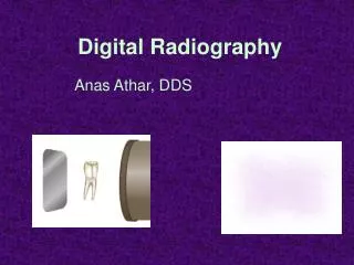
Direct Digital Radiographyor Direct Capture Radiography Bushong Ch. 26 & 29 & Carter Ch. 6
Late 1990’s • A new approach to imaging appeared • DR or DDR or Direct Capture imaging • At the moment departments can’t go all DR they must still have F/S or CR. Do you know why?
Directed Digital Radiography(DDR) Directed digital radiography, a term used to describe total electronic imaging capturing. DR is hard-wired to the image processing system.Eliminates the need for an image plate altogether.
IMAGE CAPTURE CR • PSP – photostimulable phosphor plate • REPLACES FILM IN THE CASSETTE DR – NO CASSETTE – LIGHT or E- • Captured directly • On to a transistor, photodiode or charge-coupled device • Sent directly to a monitor
DIRECT RADIOGRAPHY • uses a TFT, CCD, or photodiode to receive image data (like bucky) • that captures and converts x-ray energy • directly into digital signal • seen immediately on monitor • then sent to PACS/ printer/ other workstations FOR VIEWING
CR imaging plate processed in a Digital Reader Signal sent to computer Viewed on a monitor DR CCD, TFT or photodiode receiver (like bucky) directly into digital signal seen immediately on monitor – CR vs DR
Digital Radiography DDR CR Direct Capture Indirect Capture Computed Radiography (CR) - PSL Direct-to-Digital Radiography (DDR)-Selenium Direct-to-Digital Radiography Silicon Scint. Laser Scanning Digitizers
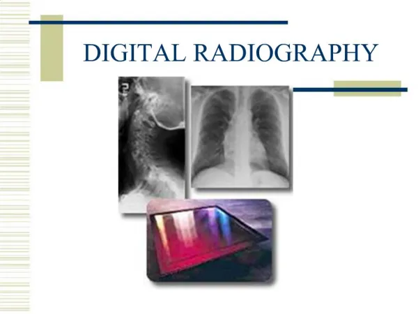
Digital Radiography Fundamentals of Digital Radiography
Flat-Panel Detectors • Flat-panel detectors consist of a photoconductor, amorphous selenium (a-Se), which holds a charge on its surface that can then be read out by a TFT. This category also includes silicon and CCD detectors.
Capture Element • Where the remnant photons are captured. • DR = Cesium iodide (CsI), Gadolium oxysulfide (GdOS), or Amorphous selenium (a-Se). • And for CR? What is the name of the compound?
Direct vs Indirect Conversion • In direct conversion, x-ray photons are absorbed by the coating material and immediately converted into an electrical signal. The DR plate has a radiation-conversion material or scintillator, typically made of a-Se. This material absorbs x-rays and converts them to electrons, which are stored in the TFT detectors.
Collection element • Collects converted x-ray signal. • Types: Photodiode, A charge-coupled device (CCD), or A thin-film transistor (TFT). • Photodiode & CCD collect light. TFT is charge sensitive and collects E-.
TFT • The thin-film transistor (TFT) is a photosensitive array made up of small (about 100 to 200μm) pixels. Each pixel contains a photodiode that absorbs the electrons and generates electrical charges.
Active Matrix Array (AMA)Pixels are read sequentially, one at a time • Each TFT or CCD detector represents a pixel • DEL = charge collecting detector element
DR • A field-effect transistor (FET) or silicon TFT isolates each pixel element and reacts like a switch to send the electrical charges to the image processor.
Amorphous Selenium • No scintillation phosphor is involved • The image-forming x-ray beam interacts directly with amorphous selenium (a-Se), producing a charged pair.
Amorphous Selenium • The a-Se is both the capture element and the converting element. • a-Se is a direct DR process by which x-rays are converted to electric signal
DDR only using amorphous selenium (a-Se) • The exit x-ray photon interact with the a-Si (detector element/DEL). Photon energy is trapped on detector (signal) • The TFT stores the signal until readout, one pixel at a time
Indirect Conversion • Indirect conversion is a two-step process: x-ray photons are converted to light, and then the light photons are converted to an electrical signal. • A scintillator converts x-rays into visible light. The light is then converted into an electric charge by photodetectors such as amorphous silicon photodiode arrays or charge-coupled devices (CCDs).
Charge-Coupled Device • CCD, which is the light-sensing element. • The CCD is a silicon-based semiconductor • has three principal advantageous imaging characteristics: sensitivity, dynamic range, and size.
Sensitivity • is the ability of the CCD to detect and respond to very low levels of visible light • This sensitivity is important for low patient radiation dose in digital imaging.
Dynamic range • is the ability of the CCD to respond to a wide range of light intensity, from very dim to very bright • DR should lower patient dose
Size • A CCD is very small, and this makes it highly adaptable to uses in radiology • The CCD itself measures approximately 1 to 2 cm, but the pixel size is an exceptional 100 × 100 μm!
Coupling Element • Transfers the x-ray signal to the collection element. • Ex: A lens or fiber optic assembly, a contact layer, or amorphous selenium.
DEL Digital Value • Digital Value depends on: • Charge collected by DEL. • Bit depth • 10 bit = 1 – 1024 • 12 bit =1 - 4096
Spatial Resolution Should be best with DR. DR is limited by pixel size
CR & DR 4000 x 4000 image only as good a monitor* 525 vs 1000 line more pixels = more memory needed to store resolution dependent on pixel size DR 4 lp/mm CR 6 lp/mm RAD 8 lp/mm Mammo 15 lp/mm IMAGE APPEARS SHARPER BECAUSE CONTRAST CAN BE ADJUSTED BY THE COMPUTER – (DIFFERENCES IN DENSITY) Image Resolution –(how sharply is the image seen)
Pixel Pitch • Spatial resolution determined by pixel pitch. • Detector element (DEL) size • 140 μm = ~3.7 lp/mm • 100 μm = ~ 5.0 lp/mm
Unlike CR plates, only the exposed pixels contribute to the image data base. • One exposure = Detector Readout
TFT Array Detectors • Detector is refreshed after exposure • If no exposures are produced. . . detector refreshed every 30 – 45 sec • Built in AEC, An ion chamber between grid and detector
Advantages/Disadvantages • CsI phosphors have high detective quantum efficiency (DQE) = lower patient dose • DQE = % of x-rays absorbed by the phosphors • a-Se only: there is no spreading of light in the phosphor = better spatial resolution
Dynamic range • is the ability of the CCD to respond to a wide range of light intensity, from very dim to very bright • DR should lower patient dose
DR • Initial expense high • very low dose to pt – due to the high DQE over CR and F/S. Fewer photons required to produce and image. • image quality of 100s using a 400s technique • Therfore ¼ the dose needed to make the image
Patient Dose • Important factors that affect patient dose • DQE: when using CsI systems • Both systems “fill factor” • The percentage of the pixel face that contains the x-ray detector. • Fill factor is approximately 80%
Viewing the Digital Image Ch. 29 Review pg 34 in carter***
Photometry • The science of the response of the human eye to light • The basic unit of photometry is the lumen (lm).
Illuminance • describes the intensity of light incident on a surface • Luminance intensity is a property of the source of light, such as a viewbox or a digital display device
Cosine Law • Is important when one is describing the luminous intensity of a digital display device. When a monitor is viewed straight on, the luminous intensity is maximum. When a monitor is viewed from an angle, the contrast and the luminous intensity are reduced.
When a digital display device is viewed from the side, illumination and image contrast are reduced.
Hard CopySoft Copy Radiology 1895Radiology 2001