Machine Group Summary
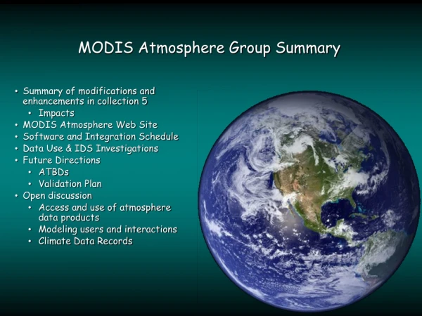
Chris Prior RAL/ASTeC and University of Oxford. Machine Group Summary . Simplified Neutrino Factory. Pion production target. Ion source. Pion to muon decay and beam cooling. Muon accelerator. Proton accelerator. Muon-to-neutrino decay ring. Detector. Earth’s interior.

Machine Group Summary
E N D
Presentation Transcript
Chris Prior RAL/ASTeC and University of Oxford Machine Group Summary
Simplified Neutrino Factory Pion production target Ion source Pion to muon decay and beam cooling Muon accelerator Proton accelerator Muon-to-neutrino decay ring Detector Earth’s interior
Previous Studies • Previous studies in Japan, USA and Europe focused on feasibility and performance • cost optimization was secondary, or ignored • U.S. Study 2a attempted to maintain performance while reducing costs • succeeded in keeping both sign muons and substantially lowering hardware cost estimate
Philosophy • Identify requirements from each area of the facility • Identify optimum parameters and performance capabilities • Decide how near we are to achieving the goals • Identify most promising ideas for further development • Facility is costly, O(€1b), so must be extremely well studied and planned if the project is to succeed. • ISS should be based on the need for optimum balance of high performance and cost. Aggregate most promising features of relevant accelerator work carried out worldwide. Also take account of developing detector and physics requirements.
Accelerator WG Organization • Accelerator study program managed by “Machine Council” • R. Fernow, R. Garoby, Y. Mori, R. Palmer, C. Prior, M. Zisman • Aided by Task Coordinators • Proton Driver: R. Garoby, H. Kirk, Y. Mori, C. Prior • Target/Capture: J. Lettry, K. McDonald • Phase Rotation/Bunching/Cooling: R. Fernow, K. Yoshimura • Acceleration: S. Berg, Y. Mori, C. Prior • Storage Ring: C. Johnstone, G. Rees • Constant liaison between task groups and Machine Council to take into account all requirements and facilitate better collaboration.
Accelerator Study Phase 1 (6 months): • Study alternative configurations; arrive at baseline specifications for a system to pursue • examine both cooling and non-cooling options • Develop and validate tools for end-to-end simulations of alternative facility concepts • Making choices requires cost evaluation • ISS will require engineers knowledgeable in accelerator and detector design Phase 2 (6 months): • Focus on selected options as prelude to subsequent World Design Study • Develop R&D list as we proceed for a credible, cost-effective design.
Pion production target Ion source Pion to muon decay and beam cooling Muon accelerator Proton accelerator Muon-to-neutrino decay ring Detector Earth’s interior Simplified Neutrino Factory
Driver-Target-Capture • A target capable of handling 4MW of proton beam power is arguably the most difficult part of a neutrino facility. • The proton driver needs to meet target capabilities in terms of pulse structure and frequency. • Driver/target/capture systems need to be optimised so that the pion/muon distribution from the target gives the maximum number of neutrinos at the detectors (1021 per annum required) • Driver energy and repetition rate are factors here.
Normalised to unit beam power Total Yield of + and − Yields (on a tantalum rod) using MARS15 and GEANT4. Better to include the acceptance of the next part of the front end
Somewhat odd behaviour for π+ < 3GeV Phase Rotator Transmission (MARS15) Doubled lines give some idea of stat. errors Optimum moves down because higher energies produce pions with momenta too high for capture
Phase Rotator Transmission (GEANT4) Transmission from GEANT4 is a factor of 2 higher because it tends to forward-focus the pions more than MARS15
Energy (heat) Deposition in Rod Scaled for 5MW total beam power; the rest is kinetic energy of secondaries. If we become limited by the amount of target heating, best energy will be pushed towards this 5-20GeV minimum (calculated with MARS15)
According to: For +: For −: 5-30GeV 5-10GeV MARS15 4-10GeV 8-10GeV GEANT4 Conclusions (Sept’05): Energy choice • Optimal ranges appear to be: Need to reconcile codes and include HARP data. Publication promised by the end of 2005.
Structure of Proton Driver Pulse • Target bombarded at ~50 Hz by a proton beam of ~1ns long bunches in a pulse of a few μsec duration. Simulations (LS-DYNA/ANSYS) show: • A 10-20% effect in radial shock as the different number of bunches in a pulse ranges from 1 to 10. • The effect of having longer bunches (2 or 3 ns) is negligible; • The effect of different length of a pulse is marked • 3μs pulse reduces radial shock, 10-30μs reduces longitudinal shock also. G. Skoro (Nufact’05)
Pion production target Ion source Pion to muon decay and beam cooling Muon accelerator Proton accelerator Muon-to-neutrino decay ring Detector Earth’s interior Simplified Neutrino Factory
Proton Driver Phase 1 • Examine candidate machine types for 4 MW operation • Linac (SPL and/or Fermilab approach) • Synchrotron (J-PARC and/or AGS approach) • FFAG (scaling and/or non-scaling) • consider • beam current limitations (injection, acceleration, activation) • bunch length limitations and schemes to provide 1-3-10 ns bunches • repetition rate limitations (power, vacuum chamber,…) • tolerances (field errors, alignment, RF stability,…) • optimization of beam energy • Consider which PD type is best suited to neutrino facility requirements (a) ideally, (b) realistically • Decide on optimum parameter set, consider existing proposals and identify which come closest to, and can be developed into, the ideal. • Define a figure of merit (muons per MW of proton beam power?)
To RHIC To Target Station High Intensity Source plus RFQ 200 MeV Drift Tube Linac BOOSTER AGS 1.2 GeV 28 GeV 0.4 s cycle time (2.5 Hz) 200 MeV 400 MeV Superconducting Linacs 800 MeV 1.2 GeV 0.2 s 0.2 s AGS Upgrade to 1 MW Possible alternative scheme with 1.5GeV FFAG • 1.2 GeV superconducting linac extension for direct injection of ~ 1 1014 protonslow beam loss at injection; high repetition rate possible further upgrade to 1.5 GeV and 2 1014 protons per pulse possible (x 2) • 2.5 Hz AGS repetition ratetriple existing main magnet power supply and magnet current feeds double rf power and accelerating gradient further upgrade to 5 Hz possible (x 2)
Superconducting Linac Parameters Linac Section LE ME HE Av Beam Pwr, kW 7.14 14.0 14.0 Av Beam Curr, mA 35.7 35.7 35.7 K.E. Gain, MeV 200 400 400 Frequency, MHz 805 1610 1610 Total Length, m 37.82 41.40 38.32 Accel Grad, MeV/m 10.8 23.5 23.4 norm rms e, p mm-mr 2.0 2.0 2.0 Proton Driver Parameters Item Value Total beam power 1 MW Protons per bunch 0.41013 Beam energy 28 GeV Injection turns 230 Average beam current 38 mA Repetition rate 2.5 Hz Cycle time 400 ms Pulse length 0.72 ms Number of protons per fill 9.61013 Chopping rate 0.75 Number of bunches per fill 24 Linac average/peak current 20/30 mA AGS 1 MW Upgrade and SC Linac Parameters • Path to 4MW: • Raise SCL energy to 1.5 GeV, AGS repetition rate to 5Hz with 2 1014 ppp. • Add post AGS accelerator to 40 GeV, raise AGS rep rate to 5 Hz with 1.4 1014 ppp.
Neutrino “Super- Beams” SY-120 Fixed-Target Damping Rings for TESLA @ FNAL With 8 GeV e+ Preacc. NUMI Off- Axis X-RAY FEL LAB 8 GeV neutrino 8 GeV Linac ~ 700m Active Length 1% LC Systems Test Main Injector @2 MW Bunching Ring Target and Muon Cooling Channel Recirculating Linac for Neutrino Factory Neutrino Target & Long-Pulse Spallation Source Short Baseline Detector Array VLHC at Fermilab Neutrinos to “Homestake” Fermilab 8 GeV SC Linac Anti- Proton
Isochronous FFAG 4 MW Proton Driver • RAL design • 5 bunches per pulse • 50 Hz repetition rate • 10 GeV • Isochronous FFAG with insertions
Simplified Neutrino Factory Pion production target Ion source Pion to muon decay and beam cooling Muon accelerator Proton accelerator Muon-to-neutrino decay ring Detector Earth’s interior
Target • Optimum target material • solid or liquid; low, medium, or high Z • Alloys, composites, “smart” materials • Production rates as function of energy for C, Ni, Hg • do reality check with HARP data if possible • Target limitations for 4 MW operation • consider bunch intensity, spacing, repetition rate • Implications of 1 v. 3 ns bunches on delivered beam • for various downstream RF systems • Superbeam v. Neutrino Factory • is a single choice of target material adequate for both?
Target Status • Solid targets • Material properties, properties under irradiation, thermal expansion • Induced shock • CNGS target test at ISOLDE: good agreement between experiment and simulation • Thermal stress waves (radial and longitudinal) • Liquid targets • 24 GeV proton beam in liquid mercury (BNL) • Heat flow • He cooling • Radiation cooling (levitated ring) • New material for each proton pulse • Chain saw, bullets, molten metal jets
Target Technologies, Issues and Plans • Molten metal targets • High pressure, high velocity, molten metal fluid dynamics • Solid targets • Effects of impurities on chemical properties • High velocity mechanics under vacuum • Compaction of beads • Component reliability or lifetime v. exchange time • Horns and 20T solenoids • Simulation codes • Go beyond simple energy deposition: shock transport, 3d models etc • Drive target scenarios to their limit through simulations – Use experimental data to guide simulations. • Optical measurement techniques in high radiation environment • Activation of components, inventory of specific activities v. time • Radioactive waste handling, internal transport, intermediate storage, end disposal • Dedicated experimental area for target tests
Planned Experimental Target Activities • MERIT (MERcury Intense Target ) • PS 24 GeV beam, 2.8 1013 protons on 1.2mm 1.2 mm beam spot • Peak energy deposition 180 J/g • Beam on target April 2007 • Proton-induced shock on a high temperature Ta cylinder with a VISAR • Graphite and Carbon-Carbon to be tested to cycles up to 1100 C • in vacuum • with forced helium • Thermal diffusivity assessment of irradiated material matrix • Damage assessment due to defect generation/growth on the irradiated specimens using ultrasonic techniques. • Material resilience to shock: Use of a high power, focused laser beam • Expose/irradiate solid targets to much higher energies. P-bar target area at FNAL is being assessed. This will shed light in the possible difference of induced irradiation damage
Superbeams • Superbeam vs. Neutrino Factory comparisons • horn vs. solenoid • can one solution serve both needs? • Comparison of Superbeam and Neutrino Factory requirements • Horn only for SB; horn or solenoid for NF (~same pion yield) • Energy range of pions of interest is wider for NF than SB • Horn geometry differs between SB and NF • SB optimised for physics → PD energy 3.5 GeV (although peak production is at 5 GeV) • To what extent can a Superbeam facility be developed into a full Neutrino Factory? • Scenarios have different requirements
at the exit of the target 2 105 pot SB Horn optimisation by S. Gilardoni nFact This new optimisation p+ p (2.2GeV) Hg Pion production
CC target Horn He OUT He IN Insulator BNL Neutrino SuperBeam Target Hollow CC target with He return
Insulator Solid CC target He IN BNL Neutrino SuperBeam Target
Simplified Neutrino Factory Pion production target Ion source Pion to muon decay and beam cooling Muon accelerator Proton accelerator Muon-to-neutrino decay ring Detector Earth’s interior
Front-End Tasks (1) • Compare performance of existing NF schemes, using common proton driver and target configurations: • Consider 6 schemes: KEK, CERN with horn, CERN with solenoid, RAL, US Study 2a, US FS2 • Use 5 beam-target combinations: Carbon with 4 and 40 GeV beams, Ta with10 GeV beam, Hg with 4 and 40 GeV beams. • Make ICOOL models of all schemes (with/without cooling) • Agree on proper figure of merit (accepted muons per MW or per pion?) • Check performance for other muon sign Conclusions will require cost comparisons, which will come later
Front-End Tasks (2) • Evaluate implications of reduced RF voltage (in case specifications cannot be met) • Consider 75% and 50% of design gradient • Re-optimize most promising designs using the smaller gradient • e.g. change lattice, amount of absorber, number of cavities • Decide what is a “practical” gradient at 5, 40, 88 and 201 MHZ? • Search for optimised phase rotation/bunching systems • RF or FFAG • adiabatic or fixed design • optimise gradients, number of frequencies, channel length • Evaluate trade-offs of cooling v. acceptance • Aim to save money (Palmer/Berg cost scaling rules)
Front-End Tasks (3) • Evaluate performance and limitations of absorbers & windows • Identify practical constraints on absorber & window choices. • Consider performance issues and limitations • Absorbers: LH2, LiH, Be. • RF windows: Be. • Consider implications of keeping both muon signs. • Carry out literature review, some engineering analysis. • What can be done with additional R&D, more money? • Prepare list of issues for each design. • Estimate resulting performance limitations. • Might require some simulation work.
CERN: 88 MHz Cavity test results Test of 88 MHz cavity for muon cooling channel Cavity conditioned at 1 Hz, 170 ms up to: 4.1 MV/m overall gradient 14.7 MV/m gap field 25.9 MV/m peak field (=2.4 Kilpatrick) Fowler-Nordheim plot of field emission current Enhancement factor b=170
Focus Coils Calorimeter Cherenkov MICE ToF Tracking Spectrometers Coupling Coils Beam Diffuser Matching Coils RFCavities Liquid Hydrogen Absorbers
m m Step II m Step III m m Step IV Step V m Step VI 2009? Step I:2007 MICE phase 1 • Constructs: muon beam line on ISIS, • and tracking and particle ID systems to measure cooling channel performance. MICE phase 2
Simplified Neutrino Factory Pion production target Ion source Pion to muon decay and beam cooling Muon accelerator Proton accelerator Muon-to-neutrino decay ring Detector Earth’s interior
Acceleration Phase 1 • Compare different schemes • RLA, scaling FFAG, non-scaling FFAG, linac • consider implications of keeping both sign muons • consider not only performance but relative costs • Prepare scenarios for different values of acceptance • transverse and longitudinal • small, medium, large (or extra-large?) • identify cost implications • Consider matching between acceleration subsystems • are there simplifications in using fewer types of machines?
Acceleration: NuFactJ • J-Parc as a proton driver. • Four scaling FFAG accelerate muons from 0.3 to 20 GeV. • No bunching, no cooling. • Single muon bunch throughout the cycle.
Acceleration: US Study IIa • AGS or Fermilab upgrade as a proton driver. • Linac and RLA up to 5 GeV. • Two non-scaling FFAG from 5 to 20 GeV. • Bunching and cooling to create a multi bunches fit into 200 MHz RF.
Acceleration: CERN NF • Linac and accumulator+compressor rings as a proton driver. • Linac and RLA up to the final energy.
Storage ring RLA, 1-3.2 GeV Linac, 0.18 GeV Linac, 0.2 to 1 GeV Isochronous FFAG 3.2 to 8, 8 to 20 GeV FFAG 3-10 GeV RCS, 0.18 to 3 GeV Blue: proton, Red: muon Acceleration: UK originated • Proton driver with FFAG. • Linac and RLA up to 3.2 GeV. • Two isochronous FFAG from 3.2 to 20 GeV in the same tunnel. • RF frequency of IFFAGI can be any, say 200 MHz.
Types of FFAG • Scaling: • Field ~rk, large apertures, tune constant, orbit variation up to 0.5m, low frequency RF 5-25 MHz. • Non-scaling: • Linear elements, large apertures, resonance crossing, tiny orbit variation, high frequency RF 200 MHz. • Isochronous: • Nonlinear fields, Qv constant, Qh varies, long insertion straights for injection/extraction/collimation, any RF frequency. • Schönauer: • Weakly isochronous, constant tune, RF ~200 MHz.
Issues • Transverse acceptance • Not clear which type of FFAG is most suitable. • Dynamic aperture • Detailed study only for isochronous • Collimation • Constant tune aids capture efficiency • Choice of acceleration method • Isochronous, gutter, RF bucket • RF frequency choice
Design progress and R&D: Scaling FFAG • POP FFAG was commissioned in 2000 and 150 MeV FFAG has been completed. • Spiral FFAG at Kyoto Univ. accelerates a beam. • Crosses integer resonance. • Resonance crossing study in POP and HIMAC.
Design Progress and R&D • Low Frequency RF • New version of MA • Shunt impedance is 10 times higher. • Q value is 30 to 50. • Frequency modulation is possible. • High Frequency RF, 201MHz cavity • SC FFAG Magnets • Fields for scaling machine • Model coil ready, 896 mm x 550 mm, NbTi/Cu, 0.9mm