Instruction Sets Chapter 2
1.04k likes | 1.32k Vues
Instruction Sets Chapter 2. COE 306: Introduction to Embedded Systems Dr. Aiman El-Maleh Computer Engineering Department College of Computer Sciences and Engineering King Fahd University of Petroleum and Minerals. Next. Computer Architecture Taxonomy ARM Instruction Set

Instruction Sets Chapter 2
E N D
Presentation Transcript
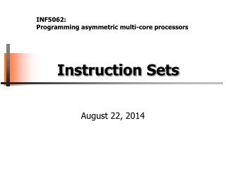
Instruction SetsChapter 2 COE 306: Introduction to Embedded Systems Dr. Aiman El-Maleh Computer Engineering Department College of Computer Sciences and Engineering King Fahd University of Petroleum and Minerals
Next . . . • Computer Architecture Taxonomy • ARM Instruction Set • PIC16F Instruction Set • TI CX55 DSP • TI C64X DSP
Von Neumann Architecture • Memory holds data, instructions • Central processing unit (CPU) fetches instructions from memory • Allows self-modifying code
Harvard Architecture • Has separate memories for data and program & allows two simultaneous memory fetches • Harvard architectures are widely used today • the separation of program and data memories provides higher performance for digital signal processing (DSP); higher memory bandwidth
Instruction Set Characteristics • The instruction set of the computer defines the interface between software modules and the underlying hardware. • Instruction set characteristics: • Fixed vs. variable length • Addressing modes • Number of operands and type • Types of operations supported • We often characterize architectures by their word length: 4-bit, 8-bit, 16-bit, 32-bit, 64-bit, etc. • Instruction set architecture: instruction set, memory, programmer accessible registers
RISC vs. CISC • Complex instruction set computer (CISC): • a variety of instructions that may perform very complex tasks; • many addressing modes. • Reduced instruction set computer (RISC): • fewer and simpler instructions; • load/store; • pipelined instructions. • Early RISC designs substantially outperformed CISC designs. • Performance gap between RISC and CISC has narrowed as CISC used RISC techniques to efficiently execute CISC instructions.
Little-Endian vs. Big-Endian • Little-endian: least-significant byte first • Big-endian: most-significant byte first Little-Endian Big-Endian
Instruction Execution • Single-issue: A single-issue processor executes one instruction at a time. • Multiple-issue • A superscalarprocessor uses specialized logic to identify at run time instructions that can be executed simultaneously • A VLIWprocessor relies on the compiler to determine what combinations of instructions can be legally executed together • VLIW is more energy-efficient than superscalar • VLIW is widely used in signal processing • Multimedia processing • Processing multiple channels of signals
ARM Instruction Set • RISC architecture: load/store • 32-bit words and instructions • ARM7: Von Neumann architecture – our focus • ARM9: Harvard architecture • Cortex-M: either architecture based on model • ARM7: 32-bit addresses, byte-addressable • Configurable endianness on power-up • Most ARM’s implement two instruction sets • 32-bit ARM Instruction Set • 16-bit Thumb Instruction Set
ARM Processor Modes • ARM has sevenbasic operating modes: • User: unprivileged mode under which most tasks run • FIQ: entered when a high priority (fast) interrupt is raised • IRQ: is used for general-purpose interrupt handling • Supervisor: is a protected mode for the operating system entered when the CPU is reset or a software interrupt instruction is executed • Abort: used to handle memory access violations • Undefined: entered when an undefined instruction is executed • System: privileged mode for the operating system. It is not entered due to an exception
The ARM Register Set • ARM has 37 registers Note: System mode uses the User mode register set
The ARM Register Set • ARM has 37 registers all of which are 32-bits long. • 1 dedicated program counter (pc) • 1 dedicated current program status register (cpsr) • 5 dedicated saved program status registers (spsr) • 30 general purpose registers • The current processor mode governs which of several banks is accessible. Each mode can access • a particular set of r0-r12 registers • a particular r13 (stack pointer, sp) and r14 (link register, lr) • the program counter, r15 (pc) • the current program status register, cpsr • Privileged modes (except System) can also access • a particular spsr(saved program status register)
Program Counter (r15) • When the processor is executing in ARM state: • All instructions are 32 bits wide • All instructions must be word-aligned • Therefore the PC value is stored in bits [31:2] with bits [1:0] undefined (as instruction cannot be halfword) • When the processor is executing in Thumb state: • All instructions are 16 bits wide • All instructions must be halfword-aligned • Therefore the PC value is stored in bits [31:1] with bits [0] undefined (as instruction cannot be byte-aligned)
Program Status Registers • Interrupt Disable bits. • I = 1: Disables the IRQ. • F = 1: Disables the FIQ. • T Bit • Architecture xT only • T = 0: Processor in ARM state • T = 1: Processor in Thumb state • Mode bits • Specify the processor mode • Condition code flags • N =Negative result from ALU • Z = Zero result from ALU • C = ALU operation Carried out • V = ALU operation oVerflowed • Sticky Overflow flag - Q flag • Architecture 5TE/J only • Indicates if saturation has occurred • J bit • Architecture 5TEJ only • J = 1: Processor in Jazelle state
Conditional Execution • Most instruction sets only allow branches to be executed conditionally. • However by reusing the condition evaluation hardware, ARM effectively increases number of instructions. • All instructions contain a condition field which determines whether the CPU will execute them. • This removes the need for many branches, which stall the pipeline. • Allows very dense in-line code, without branches.
Data Processing Instructions • Largest family of ARM instructions, all sharing the same instruction format. • Contains: • Arithmetic operations • Comparisons (no results - just set condition codes) • Logical operations • Data movement between registers • They each perform a specific operation on one or two operands. • First operand always a register - Rn • Second operand sent to the ALU via barrel shifter.
31 28 27 26 25 24 21 20 19 16 15 12 1 1 0 operand 2 cond 0 0 # opcode S Rn Rd destination register first operand register set condition codes arithmetic/logic function 25 1 1 8 7 0 #rot 8-bit immediate 1 immediate alignment 1 1 7 6 5 4 3 0 #shift Sh Rm 0 25 immediate shift length 0 shift type second operand register 1 1 8 7 6 5 4 3 0 Rs Sh Rm 0 1 register shift length Data Processing Instructions
Arithmetic Operations • Operations are: • ADD operand1 + operand2 • ADC operand1 + operand2 + carry • SUB operand1 - operand2 • SBC operand1 - operand2 + carry - 1 • RSB operand2 - operand1 • RSC operand2 - operand1 + carry - 1 • Syntax: <Operation>{<cond>}{S} Rd, Rn, Operand2 • Examples • ADD r0, r1, r2 • SUBGT r3, r3, #1 • RSBLES r4, r5, #5
Logical Operations • Operations are: • AND operand1 AND operand2 • EOR operand1 EOR operand2 • ORR operand1 OR operand2 • BIC operand1 AND NOT operand2 [i.e. bit clear] • Syntax: <Operation>{<cond>}{S} Rd, Rn, Operand2 • Examples: • AND r0, r1, r2 • BICEQ r2, r3, #7 • EORS r1,r3,r0
Comparisons • The only effect of the comparisons is to • UPDATE THE CONDITION FLAGS. Thus no need to set S bit. • Operations are: • CMP operand1 - operand2, but result not written • CMN operand1 + operand2, but result not written • TST operand1 AND operand2, but result not written • TEQ operand1 EOR operand2, but result not written • Syntax: <Operation>{<cond>} Rn, Operand2 • Examples: • CMP r0, r1 • TSTEQ r2, #5
Data Movement • Operations are: • MOV operand2 • MVN NOT operand2 Note that these make no use of operand1. • Syntax: <Operation>{<cond>}{S} Rd, Operand2 • Examples: • MOV r0, r1 • MOVS r2, #10 • MVNEQ r1,#0
The Barrel Shifter • ARM doesn’t have actual shift instructions. • Abarrel shifter provides a mechanism to carry out shifts as part of other instructions.
Second Operand:Using a Shifted Register • Multiplication by constants can often be done by using some combination of MOVs, ADDs, SUBs and RSBs with shifts. • Multiplications by a constant equal to a ((power of 2) ± 1) can be done in one cycle. • Example: r0 = r1 * 5Example: r0 = r1 + (r1 * 4) ï ADD r0, r1, r1, LSL #2 • Example: r2 = r3 * 105Example: r2 = r3 * 15 * 7Example: r2 = r3 * (16 - 1) * (8 - 1) ï RSB r2, r3, r3, LSL #4 ; r2 = r3 * 15ï RSB r2, r2, r2, LSL #3 ; r2 = r2 * 7
Second Operand: Immediate Value • No ARM instruction can contain a 32 bit immediate constant • All ARM instructions are fixed as 32 bits long • The data processing instruction format has 12 bits available for operand2 • 4 bit rotate value (0-15) is multiplied by two to give range 0-30 in steps of 2 • Values that cannot be generated in this way will cause an error.
Second Operand: Immediate Value • This gives us: • 0 - 255 [0 - 0xff] • 256,260,264,..,1020 [0x100-0x3fc, step 4, 0x40-0xff ror 30] • 1024,1040,1056,..,4080 [0x400-0xff0, step 16, 0x40-0xff ror 28] • 4096,4160, 4224,..,16320 [0x1000-0x3fc0, step 64, 0x40-0xff ror 26] • These can be loaded using, for example: • MOV r0, #0x40, 26 ; => MOV r0, #0x1000 (i.e. 4096) • To make this easier, the assembler will convert to this form for us if simply given the required constant: • MOV r0, #4096 ; => MOV r0, #0x1000 (i.e. 0x40 ror 26) • The bitwise complements can also be formed using MVN: MOV r0, #0xFFFFFFFF; assembles to MVN r0, #0
Loading 32-bit Constants • To allow larger constants to be loaded, the assembler offers a pseudo-instruction: LDRrd, =const • This will either: • Produce a MOV or MVN instruction to generate the value (if possible). • Generate a LDRinstruction with a PC-relative address to read the constant from a literal pool (Constant data area embedded in the code). • For example • LDR r0,=0xFF =>MOV r0,#0xFF • LDR r0,=0x55555555=>LDR r0,[PC,#Imm12]… … DCD 0x55555555
Multiplication Instructions • The Basic ARM provides two multiplication instructions. • Multiply • MUL{<cond>}{S} Rd, Rm, Rs ; Rd = Rm * Rs • Multiply Accumulate - does addition for free • MLA{<cond>}{S} Rd, Rm, Rs, Rn ; Rd = (Rm * Rs) + Rn • Restrictions on use: • Rd and Rm cannot be the same register • Cannot use PC. • Operands can be considered signed or unsigned • Up to user to interpret correctly.
Load / Store Instructions LDRSTRWord LDRBSTRBByte LDRHSTRHHalfword LDRSBSigned byte load LDRSHSigned halfwordload • Syntax: • LDR{<size>} {<cond>} Rd, <address> • STR{<size>} {<cond>} Rd, <address> • All of these instructions can be conditionally executed by inserting the appropriate condition code after STR / LDR. • e.g. LDRBEQ
Address Accessed • Address accessed by LDR/STR is specified by a base register plus an offset • For word and unsigned byte accesses, offsetcan be • An unsigned 12-bit immediate value (i.e. 0 - 4095 bytes).LDR r0,[r1,#8] • A register, optionally shifted by an immediate valueLDR r0,[r1,r2] LDR r0,[r1,r2,LSL#2] • Offset can be either added or subtracted from the base register:LDR r0,[r1,#-8] LDR r0,[r1,-r2] LDR r0,[r1,-r2,LSL#2]
Address Accessed • For halfword and signed halfword / byte, offset can be: • An unsigned 8 bit immediate value (i.e. 0-255 bytes). • A register (unshifted). • For all accesses, offset can be applied • before the transfer is made: Pre-indexed addressing • optionallyauto-incrementing the base register, by postfixing the instruction with an ‘!’. • after the transfer is made: Post-indexed addressing • causing the base register to be auto-incremented.
ARM ADR Pseudo-Op • Cannot refer to an address directly in an instruction. • ADRpseudo-op generates instruction required to calculate address: ADRr1,FOO • Generates value by performing arithmetic on PC.
Arithmetic Operations Example • C: x = (a + b) - c; • ARM Assembly: ADR r4,a ; get address for a LDR r0,[r4] ; get value of a ADR r4,b ; get address for b, reusing r4 LDR r1,[r4] ; get value of b ADD r3,r0,r1 ; compute a+b ADR r4,c ; get address for c LDR r2,[r4] ; get value of c SUB r3,r3,r2 ; complete computation of x ADR r4,x ; get address for x STR r3,[r4] ; store value of x
Arithmetic Operations Example • C: y =a * (b + c); • ARM Assembly: ADR r4,b ; get address for b LDR r0,[r4] ; get value of b ADR r4,c ; get address for c LDR r1,[r4] ; get value of c ADD r2,r0,r1 ; compute partial result ADR r4,a ; get address for a LDR r0,[r4] ; get value of a MUL r2,r0,r2 ; compute final value for y ADR r4,y ; get address for y STR r2,[r4] ; store y
Logical Operations Example • C: z = (a << 2) | (b & 15); • ARM Assembly: ADR r4,a ; get address for a LDR r0,[r4] ; get value of a MOV r0,r0,LSL 2 ; perform shift ADR r4,b ; get address for b LDR r1,[r4] ; get value of b AND r1,r1,#15 ; perform AND ORR r1,r0,r1 ; perform OR ADR r4,z ; get address for z STR r1,[r4] ; store value for z
ARM Branches and Subroutines • Branch:B{<cond>} label • PC relative: ±32 Mbyte range. • Branch with Link:BL{<cond>} sub_routine_label • Stores return address in LR • Returning implemented by restoring the PC from LR • MOV pc, lr
Control Flow: If Statement Example • C: if (a > b) { x = 5; y = c + d; } else x = c - d; • ARM Assembly: ; compute and test condition ADR r4,a ; get address for a LDR r0,[r4] ; get value of a ADR r4,b ; get address for b LDR r1,[r4] ; get value for b CMP r0,r1 ; compare a > b BLEfblock ; if a <= b, branch to false block
Control Flow: If Statement Example ; true block MOV r0,#5 ; generate value for x ADR r4,x ; get address for x STR r0,[r4] ; store x ADR r4,c ; get address for c LDR r0,[r4] ; get value of c ADR r4,d ; get address for d LDR r1,[r4] ; get value of d ADD r0,r0,r1 ; compute y ADR r4,y ; get address for y STR r0,[r4] ; store y B after ; branch around false block
Control Flow: If Statement Example ; false block Fblock ADR r4,c ; get address for c LDR r0,[r4] ; get value of c ADR r4,d ; get address for d LDR r1,[r4] ; get value for d SUB r0,r0,r1 ; compute c-d ADR r4,x ; get address for x STR r0,[r4] ; store value of x after ...
Control Flow: Switch Statement • C: switch (test) { case 0: … break; case 1: … } • ARM Assembly: ADR r2,test ; get address for test LDR r0,[r2] ; load value for test ADR r1,switchtab ; load address for switch table LDR r1,[r1,r0,LSL #2] ; index switch table MOV pc, r1 switchtab DCD case0 DCD case1 ...
Control Flow: For Loop • C: for (i=0, f=0; i<N; i++) f = f + c[i]*x[i]; • ARM Assembly: ; loop initiation code MOV r0,#0 ; use r0 for i MOV r8,#0 ; use separate index for arrays ADR r2,N ; get address for N LDR r1,[r2] ; get value of N MOV r2,#0 ; use r2 for f FIR FILTER
Control Flow: For Loop ADR r3,c ; load r3 with base of c ADR r5,x ; load r5 with base of x ; loop body loop LDR r4,[r3,r8] ; get c[i] LDR r6,[r5,r8] ; get x[i] MUL r4,r6,r4 ; compute c[i]*x[i] ADD r2,r2,r4 ; add into running sum ADD r8,r8,#4 ; add one word offset to array index ADD r0,r0,#1 ; add 1 to i CMP r0,r1 ; exit? BLT loop ; if i < N, continue
Examples of Conditional Execution • Use a sequence of several conditional instructions if (a==0) func(1); CMP r0,#0MOVEQ r0,#1BLEQfunc • Set the flags, then use various condition codes if (a==0) x=0;if (a>0) x=1; CMP r0,#0MOVEQ r1,#0MOVGT r1,#1 • Use conditional compare instructions if (a==4 || a==10) x=0; CMP r0,#4CMPNE r0,#10MOVEQ r1,#0