Download
1 / 31
310 likes | 471 Vues
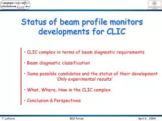
Status of beam profile monitors developments for CLIC. CLIC complex in terms of beam diagnostic requirements Beam diagnostic classification Some possible candidates and the status of their development ‘Only experimental results’ What, Where, How in the CLIC complex

E N D
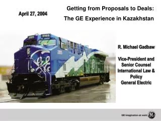
Status of beam profile monitors developments for CLIC • CLIC complex in terms of beam diagnostic requirements • Beam diagnostic classification • Some possible candidates and the status of their development • ‘Only experimental results’ • What, Where, How in the CLIC complex • Conclusion & Perspectives T. Lefevre BDI Forum April 6 , 2004
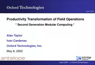
3TeV Compact LInear Collider • Damping rings • 4ps, >10mm • e-/e+ Source • 42ns, 2,424GeV • 157 bunches (400pC) • 4ps, >50mm Combiner Ring 2 • 25 Drive Beams Decelerators per linac • 1.79GeV, 144A over 56ns • 1ps, >50mm Combiner Ring 1 Delay loop Source • Drive Beam Generator • 4.5A over 92ms with an final energy of 1.79GeV: 43000 bunches (9.6nC each) • 10ps, >50mm • Main Linac • 9 1500GeV • 100fs, >1mm e- Main Linac e+ Main Linac BDS 30 GHz Power Source and distribution line T. Lefevre BDI Forum April 6 , 2004
Beam diagnostics classification Criteria based on Performances • 1- Profile measurements RMS values • More precise information on the beam characteristic • 2- Single shot measurements Sampling measurements • Do not care about the beam reproducibility (100% reproducible ?) • No need for precise timing system (tens of fs in our case) • 3- Non interceptive Interceptive • Can be used for beam study and beam control for on-line monitoring • No risk of damage by the beam itself s 1 n! T. Lefevre BDI Forum April 6 , 2004
Bunch length measurement ‘TR is generated when a charged particle passes through the interface between two materials with different permittivity (screen in vacuum)’ e- OTR Light Screen Number of OTR photons per e- ~ 5 10-3 in [400-600]nm Radiation wavelength Beam energy ~2/g # Methods Optical Transition Radiation (OTR) A huge amount of development for the past 30 years • Optical radiation • Coherent radiation • RF Pick-Up • RF Deflector • RF accelerating phase scan • Electro Optic Method • Laser Wire Scanner • Limitations : • High charge density beams : DB 3 109nC/cm2 ; MB 9 108 nC/cm2 • The thermal limit for ‘best’ screens (C, Be, SiC) is ~ 1 106 nC/cm2 • Assuming that the target has enough time to cool down between two consecutive pulses (lowering the machine repetition rate) T. Lefevre BDI Forum April 6 , 2004
Bunch length measurement ‘DR is generated when a charged particle passes through an aperture or near an edge of dielectric materials, if the distance to the target h (impact parameter) satisfies the condition : e- Slit ODR Light h Radiation wavelength Beam energy A lot of activities on ODR, but only one measurement up to now : T. Muto et al, Physical Review Letters 90 (2003) 104801 # Methods Optical Diffraction Radiation (ODR) • Optical radiation • Coherent radiation • RF Pick-Up • RF Deflector • RF accelerating phase scan • Electro Optic Method • Laser Wire Scanner • Limitations : • Not enough photons in the visible for low energy particles : E < 1 GeV for a decent impact parameter (100mm) T. Lefevre BDI Forum April 6 , 2004
Bunch length measurement Magnetic Chicane Dipole e- beam Dipole Dipole • Critical frequency : Beam curvature Beam energy # Methods Optical Synchrotron Radiation (OSR) A huge amount of development for the past 50 years • Optical radiation • Coherent radiation • RF Pick-Up • RF Deflector • RF accelerating phase scan • Electro Optic Method • Laser Wire Scanner Only available in the rings or in the magnetic chicane • Limitations : • In our case, not enough photons in the visible for low energy electrons : E > 150 MeV T. Lefevre BDI Forum April 6 , 2004
Bunch length measurement ‘Streak cameras uses a time dependent deflecting electric field to convert time information in spatial information on a CCD’ Mitsuru Uesaka et al, NIMA 406 (1998) 371 200fs time resolution obtained using reflective optics and 12.5nm bandwidth optical filter (800nm) and the Hamamatsu FESCA 200 • Limitations : Time resolution of the streak camera : • (i) Initial velocity distribution of photoelectrons : narrow bandwidth optical filter • (ii) Spatial spread of the slit image: small slit width • (iii) Dispersion in the optics # Methods Streak camera 1 • Optical radiation • Coherent radiation • RF Pick-Up • RF Deflector • RF accelerating phase scan • Electro Optic Method • Laser Wire Scanner T. Lefevre BDI Forum April 6 , 2004
Bunch length measurement ‘Non linear mixing uses beam induced radiation, which is mixed with a short laser pulse in a doubling non linear crystal (BBO,..). The resulting up frequency converted photons are then isolated and measured’ • Limitations • Laser-RF synchronization (500fs) M. Zolotorev et al, Proceeding of the PAC 2003, 2530 15-30ps electron bunches (ALS, LBNL) scanned by a 50fs Ti:Al2O3 laser # Methods n! • Non linear mixing • Optical radiation • Coherent radiation • RF Pick-Up • RF Deflector • RF accelerating phase scan • Electro Optic Method • Laser Wire Scanner T. Lefevre BDI Forum April 6 , 2004
Bunch length measurement e- beam Radiator: OTR, OSR, …. 1.5ps CCD 4.5ps Grating spectrometer 1.5ps. 200-500pC, 44MeV beam using a spectrometer with a resolution of 0.05nm/pixel P. Catravas et al, Physical Review Letters 82 (1999) 5261 # Methods s 1 • Shot noise spectrum analysis • Based on the measurement the spectrum of incoherent radiation produced by beam • The spectra are composed of spikes of random amplitude and frequency which have a characteristic width inversely proportional to the bunch length • Optical radiation • Coherent radiation • RF Pick-Up • RF Deflector • RF accelerating phase scan • Electro Optic Method • Laser Wire Scanner • Limitations : • Works only for a single bunch (or with a gated camera ) T. Lefevre BDI Forum April 6 , 2004
Bunch length measurement Coherent Transition Radiation (CTR) P. Kung et al, Physical review Letters 73 (1994) 96 • 90fs, 32MeV beam Coherent Diffraction (CDR) B. Feng et al, NIM A 475 (2001) 492–497 ; A.H. Lumpkin et al, NIM A 475 (2001) 470–475 ; C. Castellano et al, Physical Review E 63 (2001) 056501 T. Watanabe et al, NIM A 437 (1999) 1-11 & NIM A 480 (2002) 315–327 • 700fs, 35MeV beam • 470fs, 150MeV beam # Methods ‘When the wavelength of the radiation is longer than the bunch length, it is known that the coherent effect occurs inside the bunch. The longitudinal shapes of the electron bunch can be extracted by analyzing the power spectrum of the radiation’ s • Optical radiation • Coherent radiation • RF Pick-Up • RF Deflector • RF accelerating phase scan • Electro Optic Method • Laser Wire Scanner T. Lefevre BDI Forum April 6 , 2004
Bunch length measurement ‘The polychromator enables to get the spectrum directly by a single shot. The radiation is deflected by a grating and resolved by the xx-channels-detector array’ 1 # Methods n! ‘Michelson or Martin-Pupplet interferometer : • Optical radiation • Coherent radiation • RF Pick-Up • RF Deflector • RF accelerating phase scan • Electro Optic Method • Laser Wire Scanner • The radiation is split in two bunches, one is delayed by a linear stage and the intensity of the recombined bunch is measured by two detectors (one for each polarization) • The spectrum is obtained from the Fourier transform of the interferometer function’ • Limitations : • Narrow dynamic range limited by the small bandwidth sensitivity of the system element (Grating, Beam splitter, …) • Need cross calibrations • Resolution depends on the number of detectors (polychromator) T. Lefevre BDI Forum April 6 , 2004
Bunch length measurement 1 • Simple diode detectors and fixed frequency filters n! • Use of RF mixers with a sweeping oscillator • By sweeping over some given frequency range, the frequency spectrum amplitude is measured C. Martinez et al,CLIC note 2000-020 700fs bunch length on a 40MeV beam # Methods s ‘Based on the measurement of the bunch spectrum which is picked-up by a rectangular waveguide coupled to the beam pipe’ • Optical radiation • Coherent radiation • RF Pick-Up • RF Deflector • RF accelerating phase scan • Electro Optic Method • Laser Wire Scanner • Limitations : • Reproducibility of the beam charge and position • Size of the waveguides for very high frequency (>100GHz) makes the detection of very short bunches not well adapted T. Lefevre BDI Forum April 6 , 2004
Bunch length measurement R. Akre et al,SLAC-PUB-8864, SLAC-PUB-9241, 2002 • 300mm, 28GeV beam using a S-band RF deflector # Methods ‘The RF Deflector can be seen as a relativistic streak tube. The time varying deflecting field of the cavity transforms the time information into a spatial information The bunch length is then deduced measuring the beam size at a downstream position using a screen or (LWS) 1 • Optical radiation • Coherent radiation • RF Pick-Up • RF • Deflector • RF accelerating phase scan • Electro Optic Method • Laser Wire Scanner • Can extract even more information than the bunch length • ex: coupled to a bending magnet for energy dispersion along the bunch T. Lefevre BDI Forum April 6 , 2004
Bunch length measurement D. X. Wang et al, Physical Review E57 (1998) 2283 • 84fs, 45MeV beam but low charge beam # Methods ‘The electron energy is modulated by the zero-phasing RF accelerating field and the bunch distribution is deduced from the energy dispersion measured downstream using a spectrometer line’ 1 • Optical radiation • Coherent radiation • RF Pick-Up • RF Deflector • RF accelerating phase scan • Electro Optic Method • Laser Wire Scanner • Limitations : • For high charge beam Beam loading, Wakefields, … T. Lefevre BDI Forum April 6 , 2004
Bunch length measurement Bunch length is reconstructed by measuring the intensity of the polarization change as a function of laser timing n! A. M. MacLeod et al, Physical Review Letters 85 (2000) 3404 Using 12fs Ti:Al2O3 laser at 800nm and ZnTe crystal 0.5mm thick and a beam of 46MeV, 200pC, 2ps. # Methods ‘This method is based on the polarization change of a laser beam which passes through a crystal itself polarized by the electrons electric field’ • Optical radiation • Coherent radiation • RF Pick-Up • RF Deflector • RF accelerating phase scan • Electro Optic Method • Laser Wire Scanner • Limitations : • Presence of phonon (5.3THz for ZnTe) can distort the measurement for bunch length < 200fs • Radiation hardness (no problem observed up to now) • Jitter of the laser-RF synchronization T. Lefevre BDI Forum April 6 , 2004
Bunch length measurement A. M. MacLeod et al, Physical Review Letters 88 (2002) 124801 & Proceeding of the DIPAC conference, 2003. Measurements of 1.72ps bunches using a 20ps chirped laser pulse # Methods • Using a longer laser, the change in polarization will affect the laser during a time equivalent to the bunch length • Since the laser is chirped, the time info’s are converted into position using a grating spectrometer and measured by a CCD 1 • Optical radiation • Coherent radiation • RF Pick-Up • RF Deflector • RF accelerating phase scan • Electro Optic Method • Laser Wire Scanner • Limitations : • Temporal resolution depends on the chirp and the bandwidth of the laser (370fs), the resolution of the spectrometer (300fs). • 70fs temporal resolution seems feasible T. Lefevre BDI Forum April 6 , 2004
Bunch length measurement W.P Leemans et al, Physical Review Letters 77 (1996) 4182 Using a 10TW Ti:Al2O3 laser system. Detecting 5.104 10-40 keV X-rays using either an X-ray CCD and Ge detector. # Methods • Scattered photons are produced by 90 Compton scattering sending a high power ultra-short laser onto the beam • By counting the number of Compton photons as a function of the laser timing, the bunch length is measured n! • Optical radiation • Coherent radiation • RF Pick-Up • RF Deflector • RF accelerating phase scan • Electro Optic Method • Laser Wire Scanner • Limitations : • Impact of beam losses very important for electrons energy < few GeV • Jitter of the laser-RF synchronization T. Lefevre BDI Forum April 6 , 2004
Bunch length measurement Beam size measurement T. Lefevre BDI Forum April 6 , 2004
Beam size measurement • Small beam size observation S. Anderson et al, KEK-ATF-2001-08 • 5mm beam size measured using a high magnification telescope using a backward OTR screen tilted at 10° • Avoid field depth limitations • Limitations : • Spatial resolution not limited diffraction but by the optical aperture of the detection system: • with q (>> g-1) the optical aperture • Thermal limitations for high charge densities X. Artru et al, NIM AB 145 (1998) 160-168 C. Castellano and V.A. Verzilov, Physical Review STAB 1, (1998) 062801 # Methods Optical Transition Radiation 1 A huge amount of development for the past 30 years • Optical radiation • X-ray radiation • Laser Wire Scanner • Quadrupolar Pick-up T. Lefevre BDI Forum April 6 , 2004
Beam size measurement 1 • Beam Imaging: • Limitation : • Diffraction limits the measurements • for us : beam size < 100mm (damping ring) # Methods Optical Synchrotron Radiation (OSR) A huge amount of development for the past 30 years • Optical radiation • X-ray radiation • Laser Wire Scanner • Quadrupolar Pick-up T. Lefevre BDI Forum April 6 , 2004
Beam size measurement J. Urakawa et al, Proceeding of the PAC conference 1999, 256 & 2143 Measurement of 15-40mm beam size at KEK-ATF (1.19GeV ) • Limitations : • Required conditions to apply the beam size reconstruction theorem • Limited at beam size > 10mm Y. Takayama et al, Proceeding of the PAC conference 1999, 2155 # Methods Optical Synchrotron Radiation (OSR) s n! • Interferometry Method : ‘Van Citterut-Zernike theorem’ • Optical radiation • X-ray radiation • Laser Wire Scanner • Quadrupolar Pick-up • Beam size is given by the Fourier transform of the complex degree of spatial coherence, which can be obtained using double slit interferometer, measuring to the fringes visibility of the interference pattern. • The interferometer function is obtained by measuring the fringe visibility as a function of the slit width T. Lefevre BDI Forum April 6 , 2004
Beam size measurement Dipole e- beam • Si crystal oriented at the corresponding braagg angle • FZP Focal length (radius) depends on photon energy : rn = (nlf)1/2 • FZP are 0.8mm thick Tantalum absorbers spaced by 6mm on a 0.2mm Silicon Nitride (SiN) membranes r2 Monochromator FZP K. Iida et al, NIM A 506 (2003) 41-49. X-ray CCD Beam size smaller than 10mm with a resolution better than 2mm using 3.235keV X-ray and two Fresnel zone plates # Methods X-ray Synchrotron Radiation (XSR) 1 • The beam if deflected also produces X-ray radiations, not affected anymore by diffraction limitations. They are then focused using Fresnel Zone Plates onto an X-ray CCD camera. • In order to minimize aberrations in the FZP’s, a monochromator is first used to select the desired X-ray energy • Optical radiation • X-ray radiation • Laser Wire Scanner • Quadrupolar Pick-up T. Lefevre BDI Forum April 6 , 2004
Beam size measurement H. Sakai et al, Physical Review ST AB 4 (2001) 022801 & ST AB 6 (2003) 092802 10mm beam spot size at the KEK damping ring (1.28GeV) using a Fabry-perot CW optical cavity R. Alley et al, NIM A 379 (1996) 363 & P. Tenenbaum et al, SLAC-PUB-8057, 1999 • Test done a SLAC on a 30GeV, few microns size electrons beam using 350nm Nd:YAG laser and reflective optics in order to achieve a sub micron laser spot size. • Both measuring the Compton photons and/or electrons # Methods • Scattered photons are produced by 90 Compton scattering sending a high power ultra-short laser onto the beam • By measuring the number of Compton photons as a function of the laser position, the beam size is reconstructed n! • Optical radiation • X-ray radiation • Laser Wire Scanner • Quadrupolar Pick-up • Limitations : • Not efficient for the measurement of mm beam size • Cannot focused a laser better than a wavelength spot size • Need precise mm spatial alignment and stabilization (To avoid vibrations and to check laser spot size stability) • Need to study beam loss to estimate the S/N ratio T. Lefevre BDI Forum April 6 , 2004
Beam size measurement S.J. Russell,Review of Scientific Instruments, 70 (1999) 1362 & Proceeding of the 1999 PAC conference, 477, 1999 A. Jansson,Physical Review STAB & NIM A (2002) Time evolution of the beam emittance # Methods s 1 ‘Quadrupole moment is a measure of the beam ellipticity’ • Optical radiation • X-ray radiation • Laser Wire Scanner • Quadrupolar Pick-up • Suppresses the dominating intensity signal (zero order) by coupling to the radial magnetic field component. • Position contribution (first order) can not be avoided, but can be measured and subtracted. • Limitations : • Probably not well adapted to the measurement of small beam size T. Lefevre BDI Forum April 6 , 2004
Beam diagnostics classification Level of Difficulty and Reliability ‘Beam diagnostics should help you to understand how the beam behaves, it should not be the opposite’ • A detector, what for ? • Online Beam stability non intercepting and reliable • Only have access to a partial information (RMS values,..) • Beam characterization and beam physics study full information Complexity and time consuming T. Lefevre BDI Forum April 6 , 2004
Beam diagnostics classification Can we do non intercepting, single shot, beam profile measurement in an easy way ? 1 + + + = ? All in red ‘perfect system’ T. Lefevre BDI Forum April 6 , 2004
Performances of Bunch Length detectors s 1 n! Limitations • Optical radiation • Streak camera -------------------- xxxxxxx xxxxxxx > 200fs • Non linear mixing ----------------- xxxxxxx xxxxxxx Laser to RF jitter : 500fs • Shot noise frequency spectrum -- xxxxxxxxxxxxxx Single bunch detector • Coherent radiation • Interferometry ------------------- xxxxxxxxxxxxxx • Polychromator --------------------- xxxxxxxxxxxxxx • RF Pick-Up -------------------------------- xxxxxxxxxxxxxxxxxxxxx> 500fs • RF Deflector ----------------------------- xxxxxxxxxxxxxxxxxxxxx • RF accelerating phase scan -------------- xxxxxxx xxxxxxxxxxxxxx High charge beam • Electro Optic Method • Short laser pulse ------------------ xxxxxxxxxxxxxxxxxxxxx Laser to RF jitter : 500fs • Chirped pulse ----------------------xxxxxxxxxxxxxxxxxxxxx > 70fs • Laser Wire Scanner ---------------------- xxxxxxxxxxxxxxxxxxxxx Laser to RF jitter : 500fs T. Lefevre BDI Forum April 6 , 2004
Performances of Beam size detectors s 1 n! Limitations • Optical radiation • OTR ------------------------ xxxxxxx xxxxxxx xxxxxxxFor high current density • & high beam energy • OSR imaging --------------- xxxxxxx xxxxxxx xxxxxxx< 100mm beam size • OSR interferometer ------ xxxxxxx xxxxxxx xxxxxxx < 10mm beam size • X-ray radiation ------------------- xxxxxxxxxxxxxxxxxxxxx Only for Ring or magnetic chicane • Laser Wire Scanner -------------- xxxxxxxxxxxxxxxxxxxxxFor low current density & • low beam energy • Quadrupolar pick-up -------------- xxxxxxxxxxxxxxxxxxxxxFor small beam size T. Lefevre BDI Forum April 6 , 2004
My opinion up to now Bunch length measurement Beam size measurement ‘Less solutions than for bunch length’ • High resolution for precise beam study • High resolution for precise beam study • RF Deflector • OTR (low charge density) • Electro Optic Method • (chirped laser pulse) • Laser wire scanner • (high energy linac and ring) • Reliability and simplicity for beam operation • (non-interceptive method) • X-ray imaging (ring) • RF pick-up T. Lefevre BDI Forum April 6 , 2004
Potential use on CLIC MB Linac Not a lot of good candidates ! for the DB linac & for the DB Decelerator MB Damping rings MB Source BDS DB Rings T. Lefevre BDI Forum April 6 , 2004
Perspectives • Degradable detector • ‘Kalachnikov’ : bullet scanner • Drive beam size monitors ? • Neutral beam scanner C. Dimopoulou, PS/BD note 99-12 • Plasma target as forward OTR radiator already observed at LBNL not published yet • XTR & XDR : • Backward radiation is reflected by the material up to frequency ~ plasma frequency wp • Forward radiation is emitted at frequencies up to gwp • To avoid diffraction limitations in the Main beam linac K.A. Ispirian, NIM A 522 (2004) 5–8 M.A. Piestrup, et al., Phys. Rev. A 45 (1992) 1183. mm size bullet Beam loss detector e- T. Lefevre BDI Forum April 6 , 2004