
X-ray Correlation Spectroscopy Instrument
E N D
Presentation Transcript
X-ray Correlation Spectroscopy Instrument Aymeric Robert – XCS Instrument Scientist LCLS Facilities Advisory Committee Meeting June 17, 2008 Team Leaders : Brian Stephenson Gerhard Grübel Karl Ludwig Lead Engineer: Eric Bong
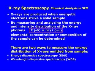
X-ray Photon Correlation Spectroscopy Coherent X-rays Coherent Scattering i.e. Speckles • Characterizing the time fluctuations of speckle patterns • (scattering patterns produced by the coherent illumination of the sample) • Characterizing the underlying dynamics of the system
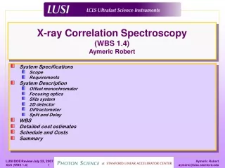
XCS Science : the mystery of the XPCS area XPCS in Grazing Incidence 2D-XPCS with CCD 1D-XPCS with autocorrelator
X-ray Photon Correlation Spectroscopy • XPCS is a “photon hungry “ technique ! • Limited by : • coherent flux • degree of coherence • detector performances • beam damages
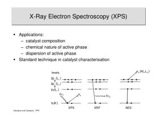
High Time–average Brilliance Rep. Rate 120 Hz Sequential Mode XCS Science @ LCLS LCLS Parameters Full Transverse Coherence 8 and 24 keV Dedicated 2D-Detector
D t Intensity autocorrelation function D t D t D t D t 4 D t 3 2 1 1 2 • Time-average Brilliance • 10 ms < tC < hrs • Large Q’s accessible 3 4 Sequential XCS
Ultra Fast Mode High Time–average Brilliance Rep. Rate 120 Hz Sequential Mode High Peak Brilliance Short pulse duration 230fs XCS Science @ LCLS LCLS Parameters Full Transverse Coherence 8 and 24 keV Dedicated 2D-Detector
Peak Brilliance & Pulse Duration • pulse duration < tC< several ns • Large Q’s accessible Ultrafast XCS : Split & Delay
FAC report Oct 07 4.2.5. XCS Instrument Aymeric Robert described the progress on designing the x-ray correlation spectroscopy (XCS) instrument. The design of this instrument is relatively mature since it builds on existing successful programs at third-generation synchrotron facilities and is scheduled to be the last commissioned. The greatest uncertainties revolve around the split and delay, x-ray monochromator and the x-ray detector. An MoU as been entered into with DESY to develop this system and a first instrument has been tested on the Troika beamline at ESRF. This instrument will need to be extended to operate at a variety of photon energies. The detector is anticipated to be a pixel array detector being developed at Brookhaven National Laboratory. The development of this detector appears to have appropriate progress. The committee recommends that the XCS staff retain flexibility in their designs to facilitate change as opportunities and problems are discovered.
XCS Instrument Schedule Instrument will operate in the 6-25 keV photon energy range JULY 2008
XCS Instrument Concept Photon Shutter Primary Slits Diagnostics Monochromator Secondary Slits Diagnostics Transport Tunnel Split and Delay Focusing Lenses Attenuators Photon Shutter Local Optics Diagnostics Slits Diagnostics CXI Station FEH Hutch 4 Diffractometer Wide Angle Detector Stage Small Angle Detector Stage
XCS Instrument @ LCLS Near Experimental Hall X-ray Transport Tunnel (200m long) XPP AMO (LCLS) XCS CXI Endstation Source to Sample distance : ~ 420 m Far Experimental Hall
Far Experimental Hall Lab Area XCS Control Room High Energy Density X-ray Correlation Spectroscopy Coherent X-ray Imaging
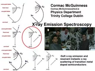
XCS Monochromator • Same design constrains than the XPP Monochromator, except that the stability requirements are larger • Thin/transmissive crystals situation still unclear in terms of availability/performance and coherence preservation. • The temporary use of a “ conventional (small offset)” non-monolithic channel-cut monochromator is investigated, while designing the large offset monochromator.
G. Grübel W. Roseker Split & Delay Unit • Provided by DESY/SLAC MoU • Prototype existing • 1st Commissioning May 07 (ESRF, Troika beamline) • pulse duration < delay < 3 ns • based on Si(511) • E=8.389 keV • Last commissioning May 08 • PhD Examination June 08 There is still the need for the development of the next generation of split & delay ( in vacuum/tunable wavelength), but not in the scope of XCS
4-circle diffractometer with local detector Massive granite base-plate for stability and vibration purpose HED CXI Restriction to nearly horizontal scattering plane Airpads to get out of the beam path with clear floor area • Standard 4-circle: • θ-rotation • local 2θ-arm • tilts (χ,φ) • translation (X,Y,Z) J.Delor • Compatibility with sample environments • SAXS chamber • Goniometer head • Low-T cryostat • High-T furnace • Others…
Different options for WAXS detector stage :Requirements CXI-Transfer Line 600mm 2θ 7-8m • Sample detector Distances • 3.5-4m (tbd) • 7.5-8m Wide Angle Detector Stage “WAXS 2θ-arm” 2θ up to 55º
ID28, IXS HERIX, sector 30 Spring-8/ESRF/APS Existing Designs
Design Comparison • 2θ=55º • 10m long • Fixed Point of rotation • Real rotation • Airpad motion with granite support A.Q.R. Baron, Y. Tanaka, S. Goto, K. Takeshita, T. Matsushita and T.Ishikawa,The Journal of Physics and Chemistry of Solids 61, (2000) 461-465.
Design Comparison ID28, IXS 2θ≈50º 7-12m long Point of rotation Lateral motion of the point of rotation with diffractometer Real rotation Translation stages
HERIX, sector 30 Design Comparison 2θ≈30º 9m long NO Point of rotation Lateral motion of the point of rotation Translation stages Software control of COR centering
Proposed XCS Design APS-HERIX-Design based 2θ up to 55º Up to 8m long NO “real” Point of rotation Lateral motion of the pseudo point of rotation by software Translation stages No contact with the diffractometer Flexible instrument with capability of accommodating any sample environment
Proposed XCS Design HED CXI 2θ
Summary • Monochromator : potential use of a temporary non-monolithic channel cut while designing and building the large offset one (tbd). • Diffractometer design allowing flexibility for accommodating very large sample environments/devices • WAXS detector stage flexible design : • APS/HERIX based design • pseudo rotation control by software • Multiple COR positions possible • separated from the diffractometer ( no point of rotation),\ • based on 2-long translations