Download
1 / 42
420 likes | 763 Vues
Analysis of Fluid Flow in Axial Re-entrant Grooves with Application to Heat Pipes. Vikrant Damle B.S., Pune University, 1999 Advisor: Dr. Scott K. Thomas. Outline. Motivation Introduction Mathematical Model Numerical Model Numerical Model Validation Parametric Analysis

E N D
Analysis of Fluid Flow in Axial Re-entrant Grooves with Application to Heat Pipes Vikrant Damle B.S., Pune University, 1999 Advisor: Dr. Scott K. Thomas
Outline • Motivation • Introduction • Mathematical Model • Numerical Model • Numerical Model Validation • Parametric Analysis • Effect of Groove Fill Amount • Capillary Limit Analysis for a Re-entrant Groove Heat Pipe • Conclusions
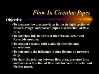
Motivation • Previous researchers assumed that the pressure drop within the liquid in a re-entrant groove could be modeled as flow within a smooth tube (Poiseuille number, Po = f Re =16) • Based on previous studies of flow in grooves with shear stress at the liquid-vapor interface, it was postulated that this assumption could lead to significant errors in pressure drop calculations • To the authors’ knowledge, the flow in re-entrant grooves has never been modeled in the open literature
Introduction • Heat pipes provide high heat transfer rates with self-regulating cooling characteristics • For optimal performance, the capillary pumping pressure should be high with low axial pressure drop • Small groove openings for small meniscus radii • Large hydraulic diameter • Minimize liquid-vapor interaction • Re-entrant grooves give good results due to their geometry
Introduction, cont. Re-entrant grooves located around the pipe circumference Monogroove heat pipe using a single re-entrant groove
MathematicalModel • Purpose • Analyze the fully-developed flow in a re-entrant groove by determining velocity profiles as function of groove geometry, applied liquid-vapor shear stress and groove fill amount • Assumptions • Steady state, fully developed laminar flow • Constant properties • Shear stress at the liquid-vapor interface is uniform across the meniscus
Numerical Model • A finite element code was used to solve the elliptic Poisson equation • The fluid flow problem was solved as a heat conduction problem • Flat plate of uniform thickness, steady state, constant properties, uniform internal volumetric heat generation • Results were grid independent to <1% when the number of elements were doubled • The numerical model was validated using existing solutions in the archival literature
Numerical Model Validation Comparison of present solution with Shah and London The present solution is in agreement with Shah and London with a maximum difference of 1.4% Circular sector duct Po vs 2alpha
Numerical Model Validation, cont. Comparison of present solution with DiCola The maximum difference is 1.2% for tau_lv = - 0.1, 0.0 and 1.0, and 0.1 < beta < 1.0 Rectangular groove Po vs beta
Numerical Model Validation, cont. Comparison of present solution with Romero and Yost Triangular groove For gamma = 5o and 60o and 0.1o < phi < 80o, the maximum difference was 2.6% Po vs phi
Numerical Model Validation, cont. Comparison of present solution with Thomas et al. Sinusoidal groove (beta = 0.5, Wl*/2 = 0.25) phi = 72.34o (Flat meniscus) tau_lv = 2.0 Po vs tau_lv Po vs phi
Numerical Model Validation, cont. Comparison of present solution with Thomas et al. Trapezoidal groove (beta = 1.0, theta = 30o) phi = 60o (Flat meniscus) tau_lv = 5.0 Po vs tau_lv Po vs phi
Numerical Model Validation, cont. • Agreement between the present solution and by Thomas et al. for sinusoidal and trapezoidal grooves is excellent when the liquid surface is flat • As phi decreases, the agreement is poor • This is due to the approximation used by Thomas et al. (countercurrent shear stress normal to z* for liquid meniscus) • Using the finite element method, it is possible to apply countercurrent shear stress normal to the liquid meniscus for any value of meniscus radius • Thus solution obtained by finite element method is more accurate
Parametric Analysis • Independent variables • Liquid-vapor shear stress • Slot width • Groove height • Fillet radius • Dependent variables • Mean velocity • Poiseuille number • Volumetric flow rate
Parametric Analysis, cont. tau_lv = -2.5 (Countercurrent shear stress) tau_lv = 0.0 (No shear stress) • Maximum velocity inside circular region • Maximum velocity less than tau_lv=0.0 • Liquid at the interface forced in the opposite direction (To scale: H* = 1.75, Hl* = 2.75, Rf* = 0.1, W*/2 = 0.5, phi = 90o)
Parametric Analysis, cont. 1.0 < H* < 4.0 Po vs tau_lv Mean velocity vs tau_lv • Mean velocity is linear with tau_lv • Mean velocity decreases with tau_lv due to increase in flow resistance • Po increases monotonically with tau_lv (Po ~1/v_mean) • Po increases dramatically for H* < 1.5 (l-v interface is closer to circular region) • Flow rate decreases with tau_lv due to decrease in v_mean Volumetric flow rate vs tau_lv (Hl* = H* + 1, Rf* = 0.1, W*/2 = 0.5, phi = 90o)
Parametric Analysis, cont. 0.05 < W*/2 < 0.90 Mean velocity vs H* Po vs H* • Mean velocity is weak function of H* for range of half slot width • The Po approaches 16 as H* tends to 1 and W*/2 tends to 0 (Smooth circular tube solution) • Flow rate increases with H* Volumetric flow rate vs H* (Hl* = H* + 1, Rf* = 0.1, phi = 90o, tau_lv = 0.0)
Parametric Analysis, cont. 1.0 < H* < 4.0 Mean velocity vs W*/2 Po vs W*/2 • Mean velocity affected by slot width more significantly as the groove height increases • Po increases substantially with slot width and becomes nearly constant • Volumetric flow rate is a monotonic function of slot width Volumetric flow rate vs W*/2 (Hl* = H* + 1, Rf* = 0.1, phi = 90o, tau_lv = 0.0)
Parametric Analysis, cont. 0.1 < W*/2 < 0.5 Mean velocity vs Rf* Po vs Rf* Mean velocity, Po and volumetric flow rate are weak functions of fillet radius Volumetric flow rate vs Rf* (H* = 2.0, Hl* = 3.0, phi = 90o, tau_lv = 0.0)
Parametric Analysis, cont. 0.0 < Rf* < 1.0 W*/2 = 0.1 W*/2 = 0.3 W*/2 = 0.4 W*/2 = 0.5 W*/2 = 0.2
Effect of Groove Fill Amount For Evaporation • Groove is initially full (phi = 90o) • Contact angle decreases until phi = phi_0(minimum contact angle) • Meniscus detaches from top of groove • In fillet region, liquid cross-sectional area decreases and meniscus radius increases dramatically • In the lower circular region, meniscus may become convex instead of concave, depending on phi phi_0 = 10o phi_0 = 40o (To scale: H* = 1.75, W*/2 = 0.5, Rf* = 0.1)
Effect of Groove Fill Amount, cont. • Liquid cross-sectional area vs Hl* • Area decreases dramatically in the fillet region for small change in height of the meniscus attachment point. • For smaller values of phi_0, decrease in the liquid area is more significant in fillet and circular region Liquid cross-sectional area vs Hl* 0 < phi_0 < 40o • Meniscus radius vs Hl* • Rm* is constant in the fillet region • Rm* increases dramatically in the circular region Meniscus radius vs Hl*
Effect of Groove Fill Amount, cont. • As liquid recedes into the groove, mean velocity increases to maximum and then decreases to zero • Po is relatively constant in slot region, decreases in the fillet region, increases in circular region • Flow rate decreases steadily in slot region and then decreases rapidly in fillet region Mean velocity vs Hl* 0 < phi_0 < 40o Po vs Hl* Volumetric flow rate vs Hl*
Effect of Groove Fill Amount, cont. • As liquid recedes into the groove, mean velocity increases to maximum and then approaches zero • Po is nearly constant • Flow rate for all the meniscus contact angles studied here nearly collapse to a single curve Mean velocity vs Al*/Ag* 0 < phi_0 < 40o Po vs Al*/Ag* Volumetric flow rate vs Al*/Ag*
Capillary Limit Analysis for a Re-entrant Groove Heat Pipe • Objective • Develop an analytical capillary limit prediction model using the results of the numerical analysis • Assumptions • Fluid properties vary with temperature • Meniscus radius and liquid height constant along heat pipe length • Zero gravity condition • Negligible liquid-vapor shear stress
Capillary Limit Analysis, cont. Re-entrant Groove Heat Pipe Specifications
Capillary Limit Analysis, cont. • Capillary limit attains maximum value in the slot region • Decreases dramatically in the circular region • Shows the critical nature of fluid fill amount in heat pipes with re-entrant groove Ethanol Heat transportvs groove fill ratio Water Heat transportvs groove fill ratio
Conclusions • The finite element solution was faster and more accurate than previous method • Easy to apply the shear stress boundary conditions • Poiseuille number was relatively unaffected by fillet radius in comparison with groove height and width • Volumetric flow rate was fairly constant with slot half width for groove height ranging from 1.0 < H* < 4.0 • The capillary limit attained maximum value in slot region and decreased dramatically as meniscus receded into circular region