Understanding AC Signal Interactions with DC Bias in Experimental Resonator Techniques
This study explores the application of AC signals with a 180° phase shift in conjunction with DC bias voltages to enhance the performance of suspended structures. The technique utilizes alternating currents in comb drives to optimize force and reduce out-of-plane levitation. Through a higher frequency carrier signal, movement is sensed via measured DC bias currents. The nonlinear response of resonators is analyzed under varying pressures in a vacuum environment, revealing challenges in pinpointing resonance frequencies at higher pressures due to broad resonance peaks.

Understanding AC Signal Interactions with DC Bias in Experimental Resonator Techniques
E N D
Presentation Transcript
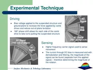
AC Signal DC Bias AC Signal (180° out of phase) AC Signal (180° phase shift) AC Signal Experimental Technique Driving • Bias voltage applied to the suspended structure and ground plane to increase the force applied by comb drives and reduce out-of-plane levitation • 180° phase shift allows for each side of the comb drive to take turns pulling the suspended structure Sensing • Higher frequency carrier signal used to sense movement • The current through DC bias is measured and with demodulation and filtering, the magnitude of the signal can be found (separate from the applied signal) – therefore determining the magnitude of the rotation.
Non-linear Response of Resonators Resonance Profiles at Varying Pressure • Devices are run in vacuum environment where nonlinear response is observed. • The diagram shows the transition with pressures ranging from 150 Torr to 36 mTorr • Hard to pinpoint exact resonance frequency at higher pressures because of the wide resonance peak. • When testing, devices were approached from below the resonance frequency and raised until the desired amplitude was obtained. Pressure (Torr)