ELEC4601 Microprocessor systems Lab 3 Tutorial
ELEC4601 Microprocessor systems Lab 3 Tutorial. Interrupts . Objectives. Interrupt Interrupt controller Timer Display controller. Interrupts. 1) Understand Interrupts and their use in a microprocessor-based system

ELEC4601 Microprocessor systems Lab 3 Tutorial
E N D
Presentation Transcript
Objectives • Interrupt • Interrupt controller • Timer • Display controller
Interrupts • 1) Understand Interrupts and their use in a microprocessor-based system • “An interrupt results in the transfer of control to a new program location.” • What is the sequence of operations that occur during an interrupt? • What are the signals that appear on the bus during an interrupt cycle? • What is the Interrupt Vector Table and how is it used?
Interrupt Controller (8259A) 2) Understand the Programmable Interrupt Controller (8259A) and it’s interface to the 8086 on the SDK Board • What are the key signals that connect the 8259A to the 8086? • What is the Interrupt Mask Register and how is it used? • How are interrupt priorities handled using the 8259A? • ICW1, ICW2, ICW4, OCW1, OCW2.
Timer (8253) • 3) Understand the Programmable Interval Timer (8253) • What is the function of 8253, and how is it used? • How is the 8253 connected to the 8086 and the 8259A (review Appendix B) • How are the counters initialized and loaded? • What signals are used to clock the counters? • Do all counters use the same clock?
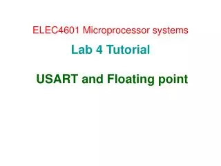
Simplified Block Diagram CLK0 IR0 • Counter 0 holds 5FB4 H = 24,500 d. What is the period for CLK0? • 10 ms • What is the data needed in counter 1 to get CLK1 period of 1 s? • 10,000 d = 2710 H Counter 1 ????H IR1 CLK1 IR2 Counter 0 ????H PCLK 2.45 MHz Counter 2 ????H CLK2 Timer 8253 PIC 8259 Further study: Appendix B
Parallel Port (8255A) and Keyboard Display Controller (8279) 4) Understand the Parallel Ports chip (8255A) • How can the 8255A be used to interface the 8086 to a D/A Converter (review Lab 2) 5) Understand the Keyboard Display Controller (8279) • How do you write to display RAM using the 8279? • How can you address the 7-segment LEDs on the SDK-86?
Seven Segment Display Table • What you need to display “0”? • a, b, c, d, e, f • Hex: 3F • What you need to display “1”? • b, c • Hex: 06 • LED_TABLE DB 3FH ; 0 DB 06H ; 1 ... How can you use it? - LDS, XLAT h h g f e d c b a Bits
Reading Materials for Prelab • From your class notes: • Communication Between I/O and CPU (pages 122-124) • From the Peripherals Handbook: • Read about the 8253, 8255, 8259, and 8279 • From the 8086 Hardware Reference Manual: • Read the section on interrupts. • Look up information for the LDS, XLAT, STI, and CLI commands
Part A Interrupt timing diagram
Part A: Prelab • Review the code in lab3A.asm • Fill in the blank comments beside the given code in provided spaces ; 8255 Setup CNTR_8255 EQU 0FFFEH ;Port control address OUTPUT_MODE EQU 0B5H ;Set up mode for port B output ; 8253 Setup COUNT_CNTR EQU 000EH ;counter control register address MODE2 EQU 74H ;__________________________________ MODE3 EQU 36H ;__________________________________ COUNT0 EQU 0008H ;counter0 address COUNT1 EQU 000AH ;counter1 address LOPT1MSEC EQU 0F5H ;__________________________________ HIPT1MSEC EQU 00H ;__________________________________ … … …
Part A: Procedure • Download Lab3A.asm to the SDK (masm, link, exe2hex) and run it (sdk,GO FE00:0.,L <filename> ,G ) • Understand what is happening. • Hint: This program initializes a couple of counters, then runs in an infinite loop • Monitor the bus signals in the Logic Analyzer and copy INTR, /INTA waveforms from into your lab procedure handbook • Answer the questions in your report
Part B Programming: timer, ic, display
Part B: Prelab • Review the code in lab3B.asm and comment the code in the blanks provided (as part A) • Write the code section to implement ISR2 which is timed using COUNT2 (counter 2) • Write LED_TABLE for 0-9 (use it in ISR2) • How can you set ISR2 to run at highest priority?
Part B: Procedure • Download Lab3B.asm given on the web to the SDK and run it as it is (do not modify yet). • This program generates a sawtooth waveform on the D/A converter and outputs a GARBAGE character to the rightmost digit of the SDK-86 display every second. Make sure it works properly before you modify the code • If everything works fine, modify Lab3B.asm according to your code to enable interrupt (ISR2) that generates a counter (0-9) in the leftmost digit of the SDK-86 display. The counter should count down from 9 to 0 and decrement every 0.5 seconds. • Your new code must not interfere with the sawtooth or the GARBAGE character routines.
Hints • Review the code for Lab#1 part D – look in appropriate sections • Understand the use and syntax of LDS, XLAT, LED_TABLE • Understand the timer block diagram (8253) – Tutorial + Appendix B • How to access ports (control and data registers) – from lab 2