Download
1 / 18
180 likes | 433 Vues
Y2K Test Beam Hardware. Upgrade of mechanics New scintillators New telescope station equipped with fast read-out Automatically read-out temperature probes New hybrid test facility Test Beam software improvement. Y2K Test Beam Mechanics.

E N D
Y2K Test Beam Hardware • Upgrade of mechanics • New scintillators • New telescope station equipped with fast read-out • Automatically read-out temperature probes • New hybrid test facility • Test Beam software improvement
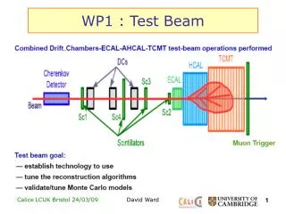
Y2K Test Beam Mechanics • New forward Black Box to host the Forward Station and the Fast Station • Detector supports • Possibility to move in vertical and horizontal with ~1mm resolution • Cool Box • Refrigerator Setup • -30 C on the fridge • ~-10 C on the detector • Dry nitrogen atmosphere • Testing detector support • Possibility to move in vertical and horizontal with ~1mm resolution • Work done in Lausanne (Raymond) Black Box Cool Box Black Box Beam Forward Station Old Telescope Testing detector Scintillator Fast station Scintillator
Y2K Test Beam Mechanics Forward station Fast station Scintillators Support Mechanics Black Box Forward Black Box Cool Box
Y2K Scintillators • Two new Scintillator Stations designed and assembled in NICKEF (Martin) • Each scintillator station has a Small and a Big sector • “Small” trigger: S1 && S2 • “Big” trigger: (S1 && S2) || (B1 && B2) Big Sector Small Sector
Y2K Test Beam Temperature Monitoring • “M70” VME board from MEN Elektronik to read-out up to 8 PT100 probes (Pavel) • Software developed in order to add temperature information to the events. • Temperature resolution 0.1 C • Some hardware problems(VME board broken) forced to manually read the temperature during the test beam. • 4 reading point, monitored at the beginning of each shift and whenever necessary. Air Temperature Support Temperature Hybrid Temperature Detector Temperature
Hybrid 80 mm pitch 50 mm pitch Fan-out Hammamatsu R detector Y2K Forward Station and Fast Station • A Forward Station has been setup to give a precise measurement behind the test detector. • R and a Phi Hammamatsu detector bonded to Viking chips • ~10 degrees tilt angle • optimize resolution • A Fast Station has been setup to improve the time correlation between the testing detectors and the telescope. • R Hammamatsu detector bonded to SCTA chips • Ceramic Fan-Out to reroute the detector to the hybrid (Raymond)
Y2K SCTA Hybrid Development • Two different hybrid design (Chesi) • SCT3: 3 chip, 50 mm pitch. Two chip read in daisy chain, one single read. • Hybrid Production in Gandi workshop • Hybrid Assembly in Millerin workshop • Chip gluing and bonding in Homna CMS bonding lab • SCT6: 6 chip, 80 mm pitch. All chip read in daisy chain Detector fan-out Command/data lines SCTA
Y2K SCTA Repeater Boards • 8 Repeater Board has been produced and assembled in Lausanne (Raymond) from Chesi design • Power supply for the SCTA • Command converter from ECL to LVDS • SCTA output Buffer with the possibility to trim the reference level. • Vref trimmer • Vcc trimmer Vref trimmer Line drivers Clock, Command and Reset Input LVDS driver
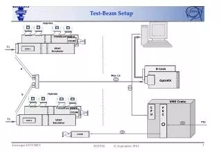
Y2K Hybrid Test Setup • An Hybrid test facility has been assembled • The ODE RB2 prototype (see Yuri talk) has been integrated in the system • The read-out of SCTA has been performed up to 20 MHz • SCTA and FADC used different 40 MHz clocks • 40 MHz readout is now possible • In all the hybrid tests the SCTA has been read at 10 MHz VME RIO controller VME Ck + Trigger TTCrx Trigger FADC Data SEQSI TTCvx TTCvi RB2 Repeater Board Hybrid Ck/Commands
Y2K SCTA Test • All hybrid are tested with the same settings • Vref 1.6 V 1.6 - 2.2 V • Vcc 4.0 V 4 - 5 V • Pream Bias 200 mA 0 - 310 mA • ADB Bias 50 mA 5-50 mA • Shaper 40 mA 0-77.5 mA • A median filter is applied to the data • Pedestal measurement • issue 100 trigger • average the outputs for each channel • Gain measurement • loop from 0 to 16 fC injected charge • for each charge issue 30 trigger • average outputs for each channel
Y2K SCTA Test • The Fast Station has been equipped with a SCT6 hybrid.
Y2K SCTA Test SCT3_3 SCT3_2
Y2K Hybrid Production: SCT3-SCT6 • 8 SCT3 ceramic hybrids has been produced and assembled • 6 SCT3 (SCT3-1 to SCT3-6) has been mounted with SCTA chips • SCT3-1: currently on MICRON 200 mm phi detector • 3 golden chips, 0 reworked chips • SCT3-4: currently on MICRON 200 mm phi detector • 2 golden chips, 1 silver chip, 2 reworked chips • The silver chip did not worked in test beam • SCT3-2: currently on Hammamatsu phi detector • 1 silver chip, 2 bad chips, 0 reworked chips • SCT3-5: currently on Hammamatsu phi detector • 2 golden chips, 1 not working chip, 2 reworked chips • SCT3-3: currently in lab • 1 silver chip, 2 bad chips, 0 reworked chips • SCT3-6: currently in lab • 8 SCT6 ceramic hybrids has been produced and assembled • 2 SCT6 has been mounted with SCTA chips • SCT6-1: currently in lab • unbonded chips • SCT6-2: currently on Fast Station • 3 gold chip, 2 silver chip, 1 unknown, 2 reworked • SCTA Yield (gold + silver chip / total number of chip)~40% • Hybrid Yield (number of produced hybrid / number of used hybrid)~60%
Y2K Detectors 96 wire bonds high irradiated side 4.2 10^14 p/cm^2 256 wire bonds low irradiated side High irradiated side 9.8 10 ^14 p/cm^2 Low irradiated side
Y2K Test Beam Hard Software • Big improvement in analysis software (see Paula talk) • Setup of Jeeves: our Butler for storing good data (Mariusz) • When a run ends, Jeeves analyzes and stages the data. • It is possible to check the quality of data instants after the run ended
Y2K Test Beam Future • August Test Beam provided with information about the silicon detector but still missing information about read-out electronics • Two read-out systems still to test in test beam environment: • Read-out chip (BEETLE, SCTA-2) • ODE • Test with the ODE Pre-Prototype can be done in immediate future • 40 MHz read-out • 60 m long cables from VELO to ODE • Test with the new read-out chip can be done in spring 2001 at the turn-on of PS • Both tests are very important for the TDR. Moreover, testing the capability to drive signals in the 60 m long cables is required to take a decision on the partitioning of the ODE • 60 m cables test successful -> rad-soft electronics in ODE • 60 m cables test unsuccessful -> rad-hard electronics in ODE • Most of the key components for the ODE test are ready or developing • ODE Board is mounted in test beam VME crate • ODE improvement for 40 MHz read-out done • Work in progress for 60 m cables and line drivers • Several good reasons to move the Test Beam Hardware to T7 test area at PS (beam available until end of November)