Three Dimensional Viewing
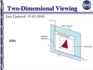
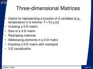
Three Dimensional Viewing. Dr. S.M. Malaek Assistant: M. Younesi. 3D Viewing. The steps for computer generation of a view of a three dimensional scene are somewhat analogous to the processes involved in taking a photograph . Orientation. Window (aperture) of the camera. Position.

Three Dimensional Viewing
E N D
Presentation Transcript
Three Dimensional Viewing Dr. S.M. Malaek Assistant: M. Younesi
3D Viewing • The steps for computer generation of a view of a three dimensional scene are somewhat analogous to the processes involved in taking a photograph.
Orientation Window (aperture) of the camera Position Camera Analogy • Viewing position • Camera orientation • Size of clipping window
Viewing Pipeline • The general processing steps for modeling and converting a world coordinate description of a scene to device coordinates:
Viewing Pipeline • Construct the shape of individual objects in a scene within modeling coordinate, and place the objects into appropriate positions within the scene (world coordinate).
Viewing Pipeline • World coordinate positions are converted to viewing coordinates.
Viewing Pipeline • Convert the viewing coordinate description of the scene to coordinate positions on the projection plane.
Viewing Pipeline • Positions on the projection plane, will then mapped to the Normalized coordinate and output device.
Viewing Coordinates • Viewing coordinates system described 3D objects with respect to a viewer. • A Viewing (Projector) plane is set up perpendicular to zv and aligned with (xv,yv). Camera Analogy
Position Specifying the Viewing Coordinate System (View Reference Point) • We first pick a world coordinate position called view reference point (origin of our viewing coordinate system). • P0 is a point where a camera is located. • The view reference point is often chosen to be close to or on the surface of some object, or at the center of a group of objects.
Specifying the Viewing Coordinate System (Zv Axis) • Next, we select the positive direction for the viewingzvaxis, by specifying the view plane normal vector, N. • The direction of N, is from thelook at point(L)to the view reference point. Look Vector
Specifying the Viewing Coordinate System (yv Axis) • Finally, we choose the up direction for the view by specifying a vectorV, called the view up vector. • This vector is used to establish the positive direction for the yv axis. • V is projected into a plane that is perpendicular to the normal vector. Up Vector
Look vector Position Look and Up Vectors • Look Vector • the direction the camera is pointing • three degrees of freedom; can be any vector in 3-space • Up Vector • determines how the camera is rotated around the Look vector • for example, whether you’re holding the camera horizontally or vertically (or in between) • projection of Up vector must be in the plane perpendicular to the look vector (this allows Up vector to be specified at an arbitrary angle to its Lookvector) Projection of up vector Up vector
Specifying the Viewing Coordinate System (xv Axis) • Using vectors NandV, the graphics package computer can compute a third vectorU, perpendicular to both Nand V, to define the direction for thexv axis. P0 P0
The View Plane • Graphics package allow users to choose the position of the view plane along the zv axis by specifying the view plane distance from the viewing origin. • The view plane is always parallel to the xvyv plane.
Obtain a Series of View • To obtain a series of view of a scene, we can keep the view reference point fixed and change the direction of N.
Simulate Camera Motion • To simulate camera motion through a scene, we can keep N fixed and move the view reference point around.
Viewing Pipeline • Before object description can be projected to the view plane, they must be transferred to viewing coordinates. • World coordinate positions are converted to viewing coordinates.
Transformation from World to Viewing Coordinates • Transformation sequence from world to viewing coordinates:
Transformation from World to Viewing Coordinates • Another Method for generating the rotation-transformation matrix is to calculate unit uvn vectors and form the composite rotation matrix directly:
Viewing Pipeline • Convert the viewing coordinate description of the scene to coordinate positions on the projection plane. • Viewing 3D objects on a 2D display requires a mapping from 3D to 2D.
Projection • Projection can be defined as a mapping of point P(x,y,z) onto its image in the projection plane. • The mapping is determined by aprojector that passes through P and intersects the view plane ( ).
Projection • Projectors are lines from center (reference) of projection through each point in the object. • The result of projecting an object is dependent on the spatial relationship among the projectors and the view plane.
Projection Parallel Projection: Coordinate position are transformed to the view plane along parallel lines. Perspective Projection: Object positions are transformed to the view plane along lines that converge to the projection reference (center) point.
Parallel Projection • Coordinate position are transformed to the view plane along parallel lines. • Center of projection at infinity results with a parallel projection. • A parallel projection preserves relative proportion of objects, but dose not give us a realistic representation of the appearance of object.
Perspective Projection • Object positions are transformed to the view plane along lines that converge to the projection reference (center) point. • Produces realistic views but does not preserve relative proportion of objects.
Perspective Projection • Projections of distant objects are smaller than the projections of objects of the same size are closer to the projection plane.
Parallel Projection • Projection vector: Defines the direction for the projection lines (projectors). • Orthographic Projection: Projectors (projection vectors) are perpendicularto the projection plane. • Oblique Projection: Projectors (projection vectors) are not perpendicular to the projection plane.
Orthographic Parallel Projection
Orthographic Parallel Projection • Orthographic projection used to produce the front, side, and top views of an object.
Orthographic Parallel Projection • Front, side, and rear orthographic projections of an object are called elevations. • Top orthographic projection is called aplanview.
Orthographic Parallel Projection Multi View Orthographic
Orthographic Parallel Projection • Axonometric orthographic projections display more than one face of an object.
Orthographic Parallel Projection • Isometric Projection: Projection plane intersects each coordinate axis in which the object is defined (principal axes) at the same distant from the origin. • Projection vector makes equal angles with all of the three principal axes. Isometric projection is obtained by aligningthe projection vector with the cube diagonal.
Orthographic Parallel Projection • Dimetric Projection: Projection vector makes equal angles with exactlytwo of the principal axes.
Orthographic Parallel Projection • Trimetric Projection: Projection vector makes unequal angles with the threeprincipal axes.
Orthographic Parallel Projection Transformation • Convert the viewing coordinate description of the scene to coordinate positions on the Orthographic parallel projection plane.
Orthographic Parallel Projection Transformation • Since the view plane is placed at position zvp along the zv axis. Then any point (x,y,z) in viewing coordinates is transformed to projection coordinates as:
Oblique Parallel Projection
Oblique Parallel Projection • Projection are not perpendicular to the viewing plane. • Angles and lengths are preserved for faces parallel the plane of projection. • Preserves 3D nature of an object.
Oblique Parallel Projection Transformation
Oblique Parallel Projection Transformation • Convert the viewing coordinate description of the scene to coordinate positions on the Oblique parallel projection plane.
Oblique Parallel Projection • Point (x,y,z) is projected to position (xp,yp) on the view plane. • Projector (oblique) from (x,y,z) to (xp,yp) makes an angle with the line (L) on the projection plane that joins (xp,yp) and (x,y). • Line L is at an angle with the horizontal direction in the projection plane.