Three Dimensional Viewing 2
560 likes | 754 Vues
Three Dimensional Viewing 2. Viewing and Perspective projections. Objectives. Develop methods to fly a camera of through scenes. Develop mathematical tools to handle perspective projection. Learn clipping techniques for perspective projections. Learn how to provide stereo views of a scene.

Three Dimensional Viewing 2
E N D
Presentation Transcript
Three Dimensional Viewing 2 Viewing and Perspective projections
Objectives • Develop methods to fly a camera of through scenes. • Develop mathematical tools to handle perspective projection. • Learn clipping techniques for perspective projections. • Learn how to provide stereo views of a scene.
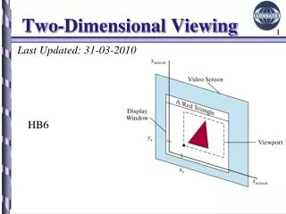
The Camera and Perspective Projection • The camera has an eye (or view reference point VRP) at some point in space. • Its view volume is a portion of a pyramid, whose apex is at the eye. The straight line from a point P to the eye is called the projector of P. (All projectors of a point meet at the eye.) • The axis of the view volume is called the view plane normal, or VPN. • The opening of the pyramid is set by the viewangleθ (see part b of the figure).
The Camera and Perspective Projection (2) • Three planes are defined perpendicular to the VPN: the near plane, the view plane, and the far plane. • Where the planes intersect the VPN they form rectangular windows. The windows have an aspect ratio which can be set in a program. • OpenGL clips points of the scene lying outside the view volume. Points P inside the view volume are projected onto the viewplane to a corresponding point P’ (part c). • Finally, the image formed on the view plane is mapped into the viewport (part c), and becomes visible on the display device.
Setting the View Volume • The default camera position has the eye at the origin and the VPN aligned with the z-axis. • The programmer defines a look point as a point of particular interest in the scene, and together the two points eye and look define the VPN as eye – look. • This is later normalized to become the vector n, which is central in specifying the camera properly. (VPN points from look to eye.)
Setting the View Volume (3) • To view a scene, we move the camera and aim it in a particular direction. • To do this, perform a rotation and a translation, which become part of the modelview matrix. • Set up the camera’s position and orientation in exactly the same way we did for the parallel-projection camera. glMatrixMode(GL_MODELVIEW); // make the modelview matrix current glLoadIdentity(); // start with a unit matrix gluLookAt(eye.x, eye.y, eye.z, look.x, look.y, look.z, up.x, up.y, up.z);
Setting the View Volume (4) • As before, this moves the camera so its eye resides at point eye, and it “looks” towards the point of interest, look. • The “upward” direction is generally suggested by the vector up, which is most often set simply to (0, 1, 0).
Camera with Arbitrary Orientation and Position • A camera can have any position and orientation in the scene. • Imagine a transformation that picks up the camera and moves it somewhere in space, then rotates it around to aim it as desired. • To do this we need a coordinate system attached to the camera: u, v, and n.
Camera with Arbitrary Orientation and Position (2) • v points vertically upward, n away from the view volume, and u at right angles to both n and v. The camera looks toward -n. All are normalized.
gluLookAt and the Camera Coordinate System • gluLookAt takes the points eye and look, and the vector up • n must be parallel to eye - look, so it sets n = eye - look • u points "off to the side", so it makes u perpendicular to both n and up: u = up x n • v must be perpendicular to n and u, so it lets v = n x u • Note that v and up are not necessarily in the same direction, since v must be perpendicular to n, and up need not be.
gluLookAt and the Camera Coordinate System (2) • Effect of gluLookAt
gluLookAt and the Camera Coordinate System (3) • The view matrix V created by gluLookAt is where dx = -eye∙u, dy= -eye∙v, dz=-eye∙n • V is postmultiplied by M to form the modelview matrix VM.
Camera with Arbitrary Orientation and Position (3) • Position is easy to describe, but orientation is difficult. • We specify orientation using the flying terms: pitch, heading, yaw, and roll. • The pitchof an airplane is the angle that its longitudinal axis (running from tail to nose and having direction -n) makes with the horizontal plane. • An airplane rolls by rotating about this longitudinalaxis; its roll is the amount of this rotation relative to the horizontal. • An airplane’s yaw is angle CW or CCW to the heading.
Camera with Arbitrary Orientation and Position (4) • Orientation is described by 3 angles: pitch, roll, and yaw.
Camera with Arbitrary Orientation and Position (5) • These terms can be used with a camera as well. The figure shows a camera with a coordinate system attached; it has u, v, and n- axes, and its origin is at position eye. The camera in part b has some non-zero roll, whereas the one in part c has zero roll. • We most often set a camera to have zero roll, and call it a “no-roll” camera. The u-axis of a no-roll camera is horizontal: that is, perpendicular to the y-axis of the world. • A no-roll camera can still have an arbitrary n direction, so it can have any pitch or heading.
Camera with Arbitrary Orientation and Position (6) • An airplane’s heading is the direction in which it is headed. (Other terms are azimuth and bearing.)
Specifying a Camera in a Program • In order to have fine control over camera movements, we create and manipulate our own camera in a program. • After each change to this camera is made, the camera tells OpenGL what the new camera is. • We create a Camera class that knows how to do all the things a camera does. • We use 2 helper classes: Point3 and Vector3.
Point3 Class class Point3{ public: float x,y,z; void set(float dx, float dy, float dz){x = dx; y = dy; z = dz;} void set(Point3& p) {x = p.x; y = p.y; z = p.z;} Point3(float xx, float yy, float zz) {x = xx; y = yy; z = zz;} Point3() {x = y = z = 0;} void build4tuple(float v[ ]) { // load 4-tuple with this color: v[3] = 1 for homogeneous v[0] = x; v[1] = y; v[2] = z; v[3] = 1.0f; } };
Vector3 Class class Vector3{ public: float x,y,z; void set(float dx, float dy, float dz){ x=dx; y=dy; z=dz;} void set(Vector3& v){ x = v.x; y = v.y; z = v.z;} void flip(){x = -x; y = -y; z = -z;} // reverse this vector void setDiff(Point3& a, Point3& b){ x =a.x - b.x; y =a.y - b.y; z =a.z - b.z;} void normalize();//adjust this vector to unit length Vector3(float xx, float yy, float zz){x = xx; y = yy; z = zz;} Vector3(Vector3& v){x = v.x; y = v.y; z = v.z;} Vector3(){x = y = z = 0;} //default constructor Vector3 cross(Vector3 b); //return this cross b float dot(Vector3 b); // return this dotted with b };
Camera Class class Camera{ private: Point3 eye; Vector3 u, v, n; double viewAngle, aspect, nearDist, farDist; // view volume shape void setModelviewMatrix(); // tell OpenGL where the camera is public: Camera(); // constructor // continued next slide
Class Camera (2) void set(Point3 eye, Point3 look, Vector3 up); // like gluLookAt() void roll(float angle); // roll it void pitch(float angle); // increase pitch void yaw(float angle); // yaw it void slide(float delU, float delV, float delN); // slide it void setShape(float vAng, float asp, float nearD, float farD); void getShape(float &vAng, float &asp, float &nearD, float &farD); };
Implementing set() void Camera:: set(Point3 Eye, Point3 look, Vector3 up) { // create a modelview matrix and send it to OpenGL eye.set(Eye); // store the given eye position n.set(eye.x - look.x, eye.y - look.y, eye.z - look.z); // make n u.set(up.cross(n)); // make u = up X n n.normalize(); u.normalize(); // make them unit length v.set(n.cross(u)); // make v = n X u setModelViewMatrix(); // tell OpenGL }
Implementing setModelViewMatrix() void Camera :: setModelviewMatrix(void) { // load modelview matrix with existing camera values float m[16]; Vector3 eVec(eye.x, eye.y, eye.z); // a vector version of eye m[0] = u.x; m[4] = u.y; m[8] = u.z; m[12] = -eVec.dot(u); m[1] = v.x; m[5] = v.y; m[9] = v.z; m[13] = -eVec.dot(v); m[2] = n.x; m[6] = n.y; m[10] = n.z; m[14] = -eVec.dot(n); m[3] = 0; m[7] = 0; m[11] = 0; m[15] = 1.0; glMatrixMode(GL_MODELVIEW); glLoadMatrixf(m); // load OpenGL’s modelview matrix }
Flying the Camera through a Scene • The user flies the camera through a scene interactively by pressing keys or clicking the mouse. • For instance, pressing ‘u’ might slide the camera up some amount, pressing ‘y’ might yaw it to the left, and pressing ‘f’ might slide it forward. • There are six degrees of freedom for adjusting a camera: it can fly in three dimensions, and it can be rotated about any of three coordinate axes. We first develop the slide() function.
Flying the Camera through a Scene (2) • Sliding a camera means to move it along one of its own axes, that is, in the u, v, or n direction, without rotating it. • Since the camera is looking along the negative n-axis, movement along n is forward or back. Similarly, movement along u is left or right, and along v is up or down. • To move the camera distance D along its u-axis, set eye to eye + Du. • For convenience, we can combine the three possible slides in a single function. slide(delU, delV, delN) slides the camera amount delU along u, delV along v, and delN along n.
Code for slide() void Camera:: slide(float delU, float delV, float delN) { eye.x += delU * u.x + delV * v.x + delN * n.x; eye.y += delU * u.y + delV * v.y + delN * n.y; eye.z += delU * u.z + delV * v.z + delN * n.z; setModelViewMatrix(); }
Flying the Camera through a Scene (3) • We want to roll, pitch, or yaw the camera (rotate it around one of its own axes). We look at rolling in detail; yaw and pitch are similar. • To roll the camera is to rotate it about its own n axis. Both the directions u and v must be rotated. • We form two new axes u’ and v’ that lie in the same plane as u and v but have been rotated through the angle α degrees.
Flying the Camera through a Scene (4) • u’ = cos(α) u + sin(α) v • v’ = -sin(α) u + cos(α) v • Finding yaw and pitch are done similarly.
Code for roll() void Camera :: roll (float angle) { // roll the camera through angle degrees float cs = cos(3.14159265/180 * angle); //convert degrees to radians float sn = sin(3.14159265/180 * angle); Vector3 t(u); // remember old u u.set(cs*t.x - sn*v.x, cs*t.y - sn*v.y, cs*t.z - sn*v.z); v.set(sn*t.x + cs*v.x, sn*t.y + cs*v.y, sn*t.z + cs*v.z); setModelViewMatrix(); }
Flying the Camera through a Scene • Code to set up perspective projection: glMatrixMode (GL_PROJECTION); glLoadIdentity ( ); gluPerspective (theta, aspect, near, far); • theta is the viewangle, aspect is W/H for the view plane, and near and far are distances to the near and far planes. • Near and far are converted to negative numbers by OpenGL.
Camera setShape() Function setShape (...) incorporates the code to set up a perspective projection: // set values of viewAngle, aspect, nearDist, farDist glMatrixMode (GL_PROJECTION); glLoadIdentity ( ); gluPerspective (viewAngle, aspect, nearDist, farDist);
Building the Camera in a Program (5) • A global Camera is declared and Camera controls are set up in the myKeyboard() function. • ‘F’ – 64 = ‘f’ • glutPostRedisplay() is used to draw the scene after camera changes. • Double-buffering is used to make the animation smooth (recall Ch. 3).
Using a Camera with SDL • There are two global objects: Camera cam; Scene scn; • In main() an SDL file is read and parsed using scn.read(“myScene.dat”). Finally, in myDisplay(void), simply replace the call to the function that draws the scene with scn.drawSceneOpenGL();
Perspective Projections of 3-D Objects • The graphics pipeline: vertices start in world coordinates; after MV, in eye coordinates, after P, in clip coordinates; after perspective division, in normalized device coordinates; after V, in screen coordinates.
Perspective Projections of 3-D Objects (2) • Each vertex v is multiplied by the modelview matrix (VM), containing all of the modeling transformations for the object; the viewing part (V) accounts for the transformation set by the camera’s position and orientation. When a vertex emerges from this matrix it is in eye coordinates, that is, in the coordinate system of the eye. • The figure shows this system: the eye is at the origin, and the near plane is perpendicular to the z-axis, located at z = -N.
Perspective Projections of 3-D Objects (3) • A vertex located at P in eye coordinates is passed through the next stages of the pipeline where it is projected to a certain point (x*, y*) on the near plane, clipping is carried out, and finally the surviving vertices are mapped to the viewport on the display.
Perspective Projections of 3-D Objects (4) • We erect a local coordinate system on the near plane, with its origin on the camera’s z-axis. Then it makes sense to talk about the point x* units right of the origin, and y* units above the origin.
Perspective Projections of 3-D Objects (5) • (Px, Py, Pz) projects to (x*, y*). • x*/Px = N/(-Pz) and y*/Py = N/(-Pz) by similar triangles. • Thus P* = (x*, y*) = N Px/(-Pz), N Py/(-Pz)).
Perspective Projection Properties • |Pz| is larger for points further away from the eye, and, because we divide by it, causes objects further away to appear smaller (perspective foreshortening). • We do not want Pz≥ 0; generally these points (at or behind eye) are clipped. • Projection to a plane other than N simply scales P*; since the viewport matrix will scale anyway, we might as well project to N.
Perspective Projection Properties (2) • Straight lines project to straight lines. Consider the line between A and B. A projects to A’ and B projects to B’. • In between: consider the plane formed by A, B, and the origin. Since any two planes intersect in a straight line, this plane intersects the near plane in a straight line. Thus line segment AB projects to linesegmentA’B’.
Example Projections of the Barn • View #1: The near plane coincides with the front of the barn. • In camera coordinates all points on the front wall of the barn have Pz = -1 and those on the back wall have Pz = -2. So any point (Px, Py, Pz) on the front wall projects to P’ = (Px, Py) and any point on the back wall projects to P’ = (Px /2, Py / 2). • The foreshortening factor is two for points on the back wall. Note that edges on the rear wall project at half their true length. Also note that edges of the barn that are actually parallel in 3D neednot project as parallel.
Example (2) • In part b, the camera has been moved right, but everything else is the same.
Example (3) • In part c, we look down from above and right on the barn.
Perspective Projection of Lines • Straight lines are transformed to straight lines. • Lines that are parallel in 3D project to lines, but not necessarily parallel lines. If not parallel, they meet at some vanishing point. • If Pz≥ 0, lines that pass through the camera undergo a catastrophic "passage through infinity"; such lines must be clipped. • Perspective projections usually produce geometrically realistic pictures. But realism is strained for very long lines parallel to the viewplane.
Projection of Straight Lines (2) • Effect of projection → on parallel lines: P = A + ct → p(t) = -N ([Ax + cxt]/[Az + czt], [Ay + cyt]/[Az + czt]) = - N/[Az + czt] (Ax + cxt, Ay + cyt). • N is the distance from the eye to the near plane. • Point A → p(0) = - N/Az (Ax, Ay). • If the line is parallel to plane N, cz = 0, and p(t) = - N/Az (Ax + cxt, Ay + cyt). • This is a line with slope cy/cx and all lines with direction c→ a line with this slope. • Thus if two lines in 3D are parallel to each other and to the viewplane, they project to two parallel lines.
Projection of Straight Lines (3) • If the line is not parallel to plane N (near plane), look at limit as t becomes∞ for p(t), which is -N/cz (cx, cy), a constant. • All lines with direction c reach this point as t becomes ∞; it is called the vanishing point. • Thus all parallel lines share the same vanishing point. • In particular, these lines project to lines that are not parallel.
Geometry of vanishing point: A projects to A’, B projects to B’, etc. Very remote points on the line project to VP as shown. Line from eye to VP becomes parallel to line AB. Projection of Straight Lines (≤)