Download
1 / 53
530 likes | 750 Vues
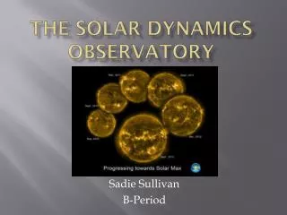
Atmospheric Image Assembly for the Solar Dynamics Observatory. Alan Title AIA Principal Investigator title@lmsal.com 650-424 4034. Outline. Quick Overview of the SDO Mission The AIA Program AIA within the Living With a Star program Science themes of the AIA investigation

E N D
Atmospheric Image Assembly for the Solar Dynamics Observatory Alan Title AIA Principal Investigator title@lmsal.com 650-424 4034
Outline • Quick Overview of the SDO Mission • The AIA Program • AIA within the Living With a Star program • Science themes of the AIA investigation • Implementing the science investigation • Managing the science data
SDO Mission Summary Objective: Launch Date: April 2008 Mission Duration: 5 years, 10 yrs of expendables Minimum Success: 5 years operation SDO spacecraft carries a suite of solar observation instruments to monitor and downlink continuous, real time science data from the Sun and distribute to science teams analysis sites Orbit: 36,000km Circular, 28.5º Geo Synch Inclined Launch Vehicle: Delta IV or Atlas V Launch Site: KSC GS Sites: SDO Dedicated
Mission Orbit Overview • The SDO geosynchronous orbit will result in two eclipse seasons with a variable daily eclipse each day • The two eclipse seasons will occur each year • During each eclipse season, SDO will move through the earth’s shadow- this shadow period will grow to a maximum of ~72 minutes per day, then subside accordingly as the earth-sun geometry moves out of the SDO eclipse season • Eclipse season effects: • Instrument • Interruption to SDO science collection • Thermal impacts to instrument optical system due to eclipse • Power • Temporary reduction or loss of power from solar arrays • Battery sizing includes eclipse impact • Thermal • S/C thermal design considerations due to bi-annual eclipses
AIA is a key component to understanding the Sun and how it drives space weather • AIA images the solar outer atmosphere: its science domain is shaded • HMI measures the surface magnetic fields and the flows that distribute it • EVE provides the variation of the spectral irradiance in the (E)UV
Themes of the AIA Investigation • Energy input, storage, and release: the 3-D dynamic coronal structure • 3D configuration of the solar corona; mapping magnetic free energy; evolution of the corona towards unstable configurations; the life-cycle of atmospheric field • Coronal heating and irradiance: thermal structure and emission • Contributions to solar (E)UV irradiance by types of features; physical properties of irradiance-modulating features; physical models of the irradiance-modulating features; physics-based predictive capability for the spectral irradiance • Transients: sources of radiation and energetic particles • Unstable field configurations and initiation of transients; evolution of transients; early evolution of CME’s; particle acceleration • Connections to geospace: material and magnetic field output of the Sun • Dynamic coupling of the corona and heliosphere; solar wind energetics; propagation of CME’s and related phenomena; vector field and velocity • Coronal seismology: a new diagnostic to access coronal physics • Evolution, propagation, and decay of transverse and longitudinal waves; probing coronal physics with waves; the role of magnetic topology in wave phenomena The needs of each of these themes determines the science requirements on the instrument and investigation.
4) Connections to Geospace Flowdown to AIA Observing Reqs. The AIA instrument design and science investigation address all over-arching science questions (1…7) in the SDO Level-1 Requirements (August 2003) What mechanisms drive the quasi-periodic 11-year cycle of solar activity? How is active region magnetic flux synthesized, concentrated & dispersed across the solar surface? How does magnetic reconnection on small scales reorganize the large-scale field topology and current systems? How significant is it in heating the corona and accelerating the solar wind? 4 5 6 7 Where do the observed variations in the Sun’s total & spectral irradiance arise, how do they relate to the magnetic activity cycle? What magnetic field configurations lead to CMEs, filament eruptions and flares which produce energetic particles and radiation? Can the structure & dynamics of the solar wind near Earth be determined from the magnetic field configuration & atmospheric structure near the solar surface? When will activity occur and is it possible to make accurate and reliable forecasts of space weather and climate? 1 2 3 Requirement Spatial Temporal Thermal Intensity Field of View x= 1Mm Accu-racy Dynamic Range t continuity logT T coverage Science theme 1 4 2 5 3 6 1) Energy Input Storage & Release Large for simul-taneous obs. of faint & bright structures - Full Disk passage ~0.3 0.7-8 MK (full corona) ~10 s Full Corona 40’-46’ Dynamic Coronal Structure 7 2) Coronal Heating & Irradiance 10% 4 2 3 7 <1 min, a few sec in flares 0.3 for DEM inv. 0.7-20 MK (full corona) >1000 Days Active Regions Thermal Structure & Emission 3) Transients 4 2 5 3 7 At least days for buildup ~0.3 for T<5MK, ~0.6 for T>5MK Majority of Disk A few sec in flares 5000 K - 20 MK >1000 in quiescent channels - Sources of Radiation & Energetic Particles 4 5 6 7 Full Disk +off-limb Continuous observing ~10 s 5000 K - 20 MK Large to study high coronal field 10% for thermal struct. ~0.3 Material & Magnetic Field Output of the Sun 4 3 ~0.5 to limit LOS confusion multi-T obs. for thermal evolution 10% for density As short as possible Continuous for discovery 5) Coronal Seismology Active Regions >10 Access to new physics
GT Science Telescope AIA Telescope Assembly = Science Telescope + GT + CEB Instrument Design Overview • Four Science Telescopes – 8 Science Channels • 7 EUV channels in a sequence of iron lines and He II 304Å • One UV Channel with 1600Å, 1700Å, white light filters • Normal incidence optics with multilayers for EUV channels • Secondary mirrors are active for image stabilization • Four Guide Telescopes (GT) • Detector is a 4096x4096 thinned back illuminated CCD • 2.5 sec readout of full CCD • 1 sec reconfigure of all mechanisms • Filter Wheels • Sector Shutter • Focal Plane Shutters • On-board data compression • Uses look-up tables • Lossless (RICE) and lossy are available
Telescope Top Level Optical Properties • Requirement 0.6 arcsec per detector pixel • 12 micron CCD pixel size • Determines final focal length = 4125.3 mm • Secondary magnification = 3 • Displacement of secondary by +/- 1 mm causes -/+ 9 mm of displacement of focal plane • Manufacturing tolerance focal lengths of secondary and primary of 0.1 % requires positioning adjustment of secondary and final focal position of +/- 3 mm and +/- 7.5 mm, respectively, to achieve desired final focal length. Back focal position 225 mm Secondary Focal Length Primary Secondary Separation 975 mm Primary Focal Length 1375 mm
AIA Telescope Assembly CCD Radiator CEB Radiator GT Pre-Amp Guide Telescope (GT) Camera Electronics Box (CEB) CEB is independently mounted to IM PZT strain gauge pre-amp A GT is mounted to each Science Telescope Vent Science Telescope (ST) Aperture Door
AIA Mounted on the IM • Four nearly identical science telescopes • Each ST has a dedicated guide telescope for ISS • CEB mounts separately to the IM • AEB is mounted within IM AIA on the IM with doors open AEB (not to scale)
AIA System Requirements • Field of View (FOV) and Pixel Size • Spatial Resolution • Temperature Coverage • Cadence • Dynamic Range • Guide Telescope Science objectives determine the top level system properties The system properties flow down to the component properties • Filters, coatings, detector performance • Mechanisms and their performance • Image Stabilization System • Electronics and Software
Field of View and Pixel Size • AIA atmospheric images shall cover a field of view of 41 arcmin (along detector axes - 46 arcmin along detector diagonal) with a sampling of 0.6 arcsec per pixel • AIA science objectives 1, 3, and 5 require whole Sun viewing • These requirements drive telescope prescription and detector size • These requirements drive the required focal length and the required resulting telescope envelop length • Sampling of 0.6 arcsec requires a 4096 x 4096 pixel detector • Derived requirements flow to telescope design (for PSF or RMS spot size) and detector MTF
Yohkoh/SXT 8 May 1992 Estimated X-ray radiance at 3 MK as observed by Yohkoh/SXT as function of limb height. AIA Field of View • Field of View: require observations to at least a pressure scale height (=0.1 Rsolar at Te=3 MK) • AIA: 41 arcmin = 1.3 P 46 arcmin = 2.0 P (see dashed lines) • AIA will observe 96% of X-ray radiance (based on Yohkoh) • AIA will observe nearly all (~98%) emission that will be in EVE’s FOV
Composite Trace Image 41 arcmin Implementation of AIA FOV • AIA will have 41 arcmin FOV along detector axes • AIA will have 46 arcmin FOV along diagonal of detector • Corners of the FOV are vignetted by the filterwheel filters
24.00 µm 2 Pixels Suncenter Solar Limb Edge of Field SDO_0011 Spatial Resolution • Telescope response must be adequate over the entire FOV • Optical Design • Ritchey- Crétien: minimizes coma – results in symmetric PSF across FOV • Spot size falls within 2x2 pixels (1.2x1.2 arcsec2) • Detector: e2v CCD has 12 m pixel size (=0.6 arcsec) focal length (4.125 m) Each channel (half telescope) fits within 2×2 pixels
AIA wavelength bands Channel †† Ion(s) Region of Atmosphere* Char. log(T) C IV 1550 Å He II 304 Å Visible - Continuum Photosphere 3.7 1600Å? Fe IX/X 171 Å 1700Å - Continuum Temperature minimum, photosphere 3.7 304Å 12.7 He II Chromosphere, transition region, 4.7 Fe XX/XXIII 133 Å 1600Å - C IV+cont. Transition region + upper photosphere 5.0 171Å 4.7 Fe IX Quiet corona, upper transition region 5.8 Fe XII 195 Å Fe XVIII 94 Å 193Å 6.0 Fe XII, XXIV Corona and hot flare plasma 6.1, 7.3 211Å 7.0 Fe XIV Active-region corona 6.3 Fe XIV 211 Å Fe XVI 335 Å 335Å 16.5 Fe XVI Active-region corona 6.4 94Å 0.9 Fe XVIII Flaring regions 6.8 131Å 4.4 Fe XX, XXIII Flaring regions 7.0, 7.2 *Absorption allows imaging of chromospheric material within the corona; ††FWHM, in Å Temperature Coverage • AIA implementation makes use of multilayer coatings on normal incidence optics with filtering to achieve desired wavelength bandpasses • EUV wavelengths selected to observe corona at required temperatures • AIA science objectives 1, 2, 3, 4 require that the temperature resolution be ΔlogT~0.3 • Selected lines of iron to minimize abundance effects • Four wavelengths have not been observed with TRACE or SOHO/EIT • One analysis technique we expect to use commonly is differential emission measure (DEM) modeling [Channel intensities: Ii=//Gi(Te)ne2(Te)dTe ]
AIA temperature coverage • EUV Wavelength selection meets AIA science objectives Dots are SOHO/CDS + Yohkoh data. Black curve is the recovered DEM using simulated AIA responses. The responses of the AIA channels are shown normalized to recovered DEM.
DEM Reconstruction Tests • Tests performed with simulated data – predicted AIA response functions show that multiple channels are necessary to constrain solution for DEM • Consistent with the fact that the solar atmosphere is emitting over a broad range of temperatures • With five channels, it is often possible to achieve solutions, but the quality of the recovered DEM improves with the number of temperature channels 4 channels (131,175,193,211) 7 channels (6 EUV+304) From Deluca et al (AIA00407)
Selection of non coronal lines • UV channel will have three filters: White light, C IV 1550, UV Continuum • White light used for ground calibration • White light used for co-alignment with HMI and other ground-based instruments • UV filters are similar to TRACE bandpasses • Study waves and field going into the corona as well as particle beams and conducted thermal energy coming down • He II 304A • Observes the chromosphere • Monitor filaments • Key driver to chemistry of the Earth’s outermost atmospheric layers EIT 304A 14 Sept 1999 Example of a prominence observed by SOHO/EIT. The upper chromosphere has a temperature of 60,000 K.
304 211 335 94 193 131 UV 171 AIA Telescopes & Wavelengths Looking at the AIA from the Sun 1600 C IV 1700 UV Cont. 4500 White Light Fe XIV He II Fe XVI +Y Fe IX Fe XII/XXIV Fe VIII/XX/XXIII Fe XVIII +Z Instrument Module / Optical Bench 4 3 2 1
Cadence: Normal and Special Ops • Regular cadence of 10 s for 8 wavelengths for full-CCD readouts allows observations of most phenomena, guaranteed coverage, ease of analysis (timing studies), and standardized software, compatible with HMI observations and EVE science needs. • But fast reconnection, flares, eruptions, and high-frequency waves require higher cadence. Within telemetry constraints, partial readouts in a limited set of wavelengths embedded in a slowed baseline program, infrequently implemented, broaden discovery potential without adverse effects to LWS goals
Filters • Entrance Filters • Must block 10-6 of out-of-bandwidth radiation • Used for wavelength selection (Al or Zr) in two telescopes (94/304; 131/335) • Filterwheel Filters • Must block 10-6 of out-of-bandwidth radiation • Wavelength selection (Al or Zr) in two telescopes (94/304; 131/335) • UV filters must have appropriate bandpasses for C IV, UV Cont, visible light
Zr & Al used to select wavelengths • Properties of zirconium and aluminum are used to select the wavelengths in two of the telescopes: 94/304 and 131/335 • Al filters are similar to that used on TRACE and STEREO/SECCHI • Zr has been developed by Luxel, but no solar flight experience
Coatings • With filter transmissions must provide ΔlogT~0.3 • Must provide adequate reflectivity to meet cadence requirements (maximum of 2.7s exposures to meet 10s/2 cadence)
Summary of filters and coatings • The choice of filters makes it possible to select wavelengths on each half of the telescope by choosing the appropriate filter except for the 193/211 telescope • Filter 2 represents a redundant filter • The Zr (3000 Å)/Poly filter in the 131/335 telescope could be used for additional attenuation during flares
AIA Detector System • CCD – 4096 x 4096, 12 micron pixels • Well depth is >150,000 electrons • 335 A channel is the limiting case for EUV wavelengths: (12.398/335)/3.65*150,000=1521 • Thinned and back illuminated for quantum efficiency at EUV wavelengths • HMI and AIA use identical cameras and CCDs except HMI CCDs are front illuminated • e2v has produced non-flight functioning devices • Cooling: Need to cool below -65C • Dark current performance • Mitigate loss of charge transfer efficiency due to radiation damage
CCD QE estimates based on SXI • AIA detector quantum efficiency is based on measurements of back-illuminated e2v devices • Experience indicate consistent QE performance within a wafer run
CCD Camera System • CEB – 8 Mpixels/sec via 2 Mpixels/sec from 4 ports simultaneously • Extension of SECCHI/STEREO cameras by RAL • Electronic design is identical to HMI • Design modifications are quite mature • Camera has 14-bit ADC • Seeking to maintain identical HMI and AIA mechanical enclosures for spares compatibility CEB
Status of CCDs and Cameras Packaged thin gate CCD CCD Status: • Three batches of devices processed • Third batch in probe testing and shows better yield • Images from first packaged device • Reviews in England • July 03 Peer Review • Feb 04 Demo Phase Review • Delivered evaluation unit to RAL in late-March • Deliver 2 evaluation units to LMSAL May 04 • Next visit to e2v in early May CEB Status: Commissioning image • Video board schematic is complete • Characterized the ghosting affect • CDS/ADC ASIC is being processed • Existing wave form generator ASIC are being packaged • Progress is being made on the mechanical interface • Reviews in England • July 03 Requirements review • Sept 03 ICD discussions at RAL • Feb 04 Proposal and status discussions • Probe image • (thin gate, room temp)
Guide Telescope • AIA has four identical guide telescopes • Noise equivalent angle of 1 arcsec • Sun acquisition range: ±24 arcmin • Linear signal range: ±95 arcsec • Same optical prescription as TRACE • Co-alignment to science telescope is <±20 arcsec • Low and high gains enable ground testing with StimTel
Guide Telescopes 1-Foot Ruler
GT Signal for Spacecraft ACS • Each GT produces high bandwidth analog pointing error signals for image motion by rotations about the Y & Z axes (pitch and yaw) • Digitized versions of the signals are used for S/C ACS pointing, housekeeping data on ISS health, high rate diagnostic data for ISS calibration • Signals from all GT’s sent to S/C with 5 Hz update frequency • S/C points to null the primary GT signal plus bias (between AIA common boresight and GT) • Bias computed periodically (monthly) and uplinked following GT & ST pointing calibrations • One will be ACS prime and the others will be redundant (all four are available to the ACS) • GT Noise Level will be determined by electrical noise, not photon noise • 5 Volt analog signal corresponds to approx. +/-100 arcsec • Digitized to 12 bits LSB = 0.05 arcsec = 1.2 milli-volts, very small • TRACE & SECCHI GT have instantaneous 1-sigma noise ~10 mV = 0.4 arcsec • Noise will be reduced by averaging samples in AIA processor
Image Stabilization System • GT analog signals are used by the image stabilization system (ISS) within the associated Science Telescope • Photo diodes and preamp circuits are redundant • No cross-strapping for ISS • Design is based on TRACE • Secondary is activated with three PZTs • Error signal provided by guide telescope PZTs
Filterwheel Assembly Aperture Door Wavelength Selector Focus Motor Shutter Assembly Cross section: mechanism locations • Requirements have been flowed down to all mechanisms • Five mechanism types: all have design heritage
Mechanism Requirements (1 of 2) • Aperture Door • Tight seal to protect entrance filters • Particle protection • Operates once on orbit • Focus Mechanism • AIA design has ±800 m range • Moves the secondary mirror • Based on the TRACE design • Shutter Mechanism • Blade diameter: 6.25 in • Minimum exposure: 5ms • Minimum cadence: 100 ms • For narrow slot or medium slot exposures TRACE door Focus Mech Design
Half Shade Aperture Selector Design Mechanism Requirements (2 of 2) • Filter wheel mechanism • Brushless DC motor with 5 positions • Filter aperture diameter: 55 mm (4 positions) • Max operational time: 1s between adjacent positions • Sets the wavelength in 3 of the four telescopes • Aperture selector (in 193/211 channel) • Only included in one telescope • Brushless DC motor/half shade • Move time: 1 s • Blade diameter: 8.3 in • Selects wavelength in 193/211 telescope
AIA response functions (1 of 2) • Computed AIA response functions show that Level 1 requirements for temperature range and sensitivity (cadence) will be met
AIA response functions (2 of 2) • Computed AIA response functions show that Level 1 requirements for temperature range and sensitivity (cadence) will be met
AIA observing times • AIA design achieves required observing times • Provides 10s or better cadence with two wavelength channels per telescope • Automatic exposure control is available to adjust shutter times for transient activity
Key Electronics and Software • The AIA science data shall not exceed of maximum data rate allocation of 67 Mbps over the IEEE 1355 high rate science data bus • Requires the use of some data compression • Electronics and software must provide observational sequence control • AIA science objectives require specific sequences (cadence, FOV, exposure time) to obtain appropriate observables • Observing sequences must be configurable • To react to changing solar conditions • Expect weekly to daily operations • Automatic exposure control must be provided CEB AEB
Electronics and Software Design • Data Compression • Will be provided using reconfigurable look-up tables • Square root binning (SRB) provides lossy compression • Amount of compression can be adjusted through updates to look-up tables • Multiple tables implemented to tune compression on a channel-by-channel basis • RICE (lossless) compression achieves 4.5 bits/pixel on 171Å TRACE images • SRB + RICE achieves 3.5 bits/pixel on 171Å TRACE images • Average SRB + RICE on all AIA images (including UV) is 3.7 bits/pixel • Provides a margin of 18% if telemetry allocation is limited to 58 Mbps • Increased allocation to 67 Mbps will improve data quality (requires less aggressive SRB algorithms) • Automatic Exposure Control (AEC) • Based on TRACE design • Adjusts exposure time to account for changing solar intensity • In 131Å channel (Fe VIII,XX) can control filterwheel for additional attenuation
Joint HMI/AIA SOC • Common aspects • Instrument commanding • Telemetry data capture (MOC to JSOC and DDS to JSOC interfaces) • Pipeline generation of Level-1 data • Distribution of data to co-investigator teams and beyond • Location of facilities • Unique requirements • HMI Higher Level Helioseismology Data Products • AIA Visualization and Solar Event Catalog
Science Coordination • The AIA team will stimulate joint observing and analysis. • Coordinated observing increases the coverage of the global Sun-Earth system (e.g., STEREO, coronagraph, wind monitors, …), provides complementary observations for the solar field (e.g., vector field, H filament data) and its atmosphere (Solar-B/EIS spectral information). And it increases interest in analysis of AIA data. • The AIA team includes PI’s and Co-I’s from several other space and ground based instruments committed to coordination (perhaps “whole fleet months”): • EVE and HMI needs have been carefully taken into account in setting plate scale, field of view, cadence, and channel selections, and in science themes. SOLAR B XRT HVMI GBO coronagr. STEREO SECCHI 2D 3D Full-Disk: Vector Field Convection Soft X-ray images for complementary T-coverage in corona CME propagation High Field Wind structure Flows (spectra) for 3-D velocities and geometry EVE Vector Field small scales H AIA SOLAR B FPP Calibration Legend: Full-Disk Chromosphere Surface Vector Field for field extrapolation On SDO Densities + Calibration SOLIS Energetic Particles AIA Co-I’s Flows (spectra) for 3-D velocities & geometry (Non) Thermal Particles Coronal Field Other FASR VLA OVRO GOES ACE RHESSI SOLAR B EIS STEREO -WAVES
Data Management Requirements • HMI data volume and processing requirement • Raw data – One 4Kx4K image each 2 seconds (telemetry = 55 Mbps) • Level-1 – set of 10 (V) or 20 (B) images to make observable • Higher Level Data Products – Projections, time-series, transforms, fits, and inversions to arrive at inferences of physical conditions in solar interior • Heritage - Similar to SOHO/MDI and NSO/GONG. All higher level products now exists as research tools. Complexity of data types very similar. Data organization the same. User community the same. Data export requirements expected to be similar in complexity and number but data volume will be larger. • AIA data volume and processing requirement • Raw data volume – Eight 4Kx4K images each 10 seconds (telemetry = 67 Mbps) • Level-1- Flat field and spike removal • Visualization – Long range coupling of active region scale processes • Solar Event Catalog – list of transients to enable “observing the archive” • Heritage– Similar to TRACE and SOHO/EIT. Complexity of data types very similar. Data organization the same. User community the same. Data export requirements expected to be similar in complexity and number but data volume will be larger.
Stanford/Lockheed GSFC H/K JSOC ops MOC Users Command Science Command H/K White Sands DDS, etc Ka Science S-band H/K Command Mission Data Flow Block Diagram
MOC DDS LMSAL House- keeping Database HMI & AIA Operations Stanford HS & Mag Pipeline Level-0 Level-1 Redundant Data Capture System AIA Interactive Image Analysis quicklook Movie Tools Primary Archive 30-Day Archive Catalog Movie Archive Event Catalog High-Level Data Import Offline Archive Offsite Archive Data Export & Web Service Science Team Forecast Centers EPO & Public JSOC Data Flow
Components AIA Science Operations • Health and Safety of AIA Instrument • Monitored via a pair of workstations • Spacecraft Commanding for Normal Operations • Done occasionally ~ a few times per week • Production of Quick-Look Data • Web based survey page with movies and science data in near real time • Catalog data • Automatic recognition • Ancillary data from other sources e.g. GOES, ACE, STEREO, Solar B, GB Observatories • Visual event recognition by quick-look observers • Surveys from Visualization Center • Production of Reference Data • DEM Maps • Potential Field Maps (from HMI) • Force Free Field Maps (from HMI) • Support of Data Access • Web pages to access data and request specific processing • Maintenance of Data Archive Catalog
JSOC Implementation - AIA Component • Instrument MOC - Monitors Heath and Safety and Sends Instrument Commands • Hardware and software developed by LMSAL as operational GSE for test and integration of HMI and AIA • Responsible for Instrument commanding, operations, health and safety monitoring • Development based on previous missions (MDI, TRACE, SXI, FPP) GSE development • Minimal operations commands sent for software uploads, calibration, and operational mode selection • Science Processing Center - Provides Data for Scientific Analysis & Quick Look • All computers, disk drives, and tape libraries in single computer system • LMSAL developed AIA quick look & calibration software based on existing TRACE systems • Some software for special science products developed by Co-Is and foreign collaborators. • Catalog uses formats developed for VSO and EGSO • AIA CPU Processing task approximately 160 times that required for TRACE • AIA On-line disk storage estimated 270 Terabytes. • On-line data available on Web in near real-time at two web sites • 2500 Terabyte Archive on robotic tape libraries for access to entire mission data base • Archive Data available via web request typically in less than 24 hours