Download
1 / 61
610 likes | 670 Vues
Understand the fundamentals of wireless communication networks, including channels, transmitters, receivers, and shared vs. dedicated mediums. Explore challenges, such as noise, signal strength, and interference, affecting mobile communication performance.

E N D
L3:Wireless Transmission Fundamentals Weijia Jia
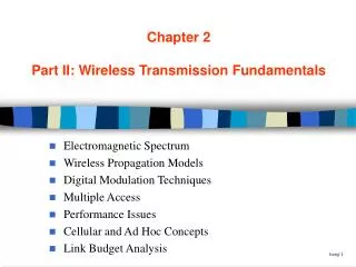
Wireless Mobile Communication Layer • Application layer • Transport layer • Network layer • Data link layer • Physical layer
You are mobile phone and mobile Internet users • You may ask: • “Why are mobile communications so expensive, and the performance so poor and no guarantee mostly?” • Mobile phone operator Co. replies: • “Data Transmission through a wireless network is totally different from transmission through a wired network. …”
Communication Channels Receiver Channel Transmitter sender Medium (channel) transmits signals from the transmitter to the receiver Wired / Wireless channels • What is communication? What is a channel? • What are the channels in a wired/wireless network? • Transmitter converts data into signals (i.e., coding and modulation) and sends them to the receiver through a channel (medium). Receiver receives the signals and converts the signals back to the original data
Wired Channels Every user accesses the network by means of a dedicated channel Switching Center or Network Access Point Dedicated Channels New user is served by a new wireline circuit Access capacity is “unlimited”. Channel length ↑ signal strength↓ Agree? NO. Not a big problem. For wired systems, we can simply install new cables to increase the capacity
Wired Channels Transmitter Wired Channel, e.g. copper wire Receiver Shielded against electromagnetic noise Too many noises? Large signal attenuation? Use repeaters Data speed too low? Upgrade to coaxial cable Data speed still too low? Upgrade to optical fiber More easy for controlling the signals for transmission
How about wireless networks? Receivers A shared transmission medium Wireless users access the network by means of a shared channel Shared Channel Base Stations (Senders) Access capacity is inherently limited. How to make the sharing? For wireless systems, the channel are shared by ALL users. Capacity cannot be increased by adding more channels
The FIRST main reason is … A SINGLE medium SHARD by ALL users What is the medium?
Wired Channels vs. Wireless Channels Dedicated Channels vs. Shared Channels
What are the problems resulting from shared medium? • Some observations in mobile communications: • Low bandwidth, high error rate, • Error-rate is location-dependent, • frequent disconnection, … • Why do we have such problems?
How do you talk (communicate) with your friend? • Wireless communication: • If he is next to you, you may talk with him directly • Wired communication: • If he is far from you, you may use a (wired) telephone • Why do not talk directly through the air? • Too far and unclear to hear • Speak louder => Create noises to others
Sharing the SAME MEDIUM creates … • NOISE problem • Propagation in ALL directions creates the signal STRENGTH problem • NOISE problem + SIGNAL STRENGTH problem => High Error Rates (Low Bandwidth), frequent disconnections, …
Where do noises come from? • Interference=>received signals are unclear due to noises • Where do noises come from? • Other transmitters: Shared medium (channels) for data transmissions from different transmitters • The same transmitter: Interferences of the signals from the same transmitter (inter-symbol Interference) • The signal itself : the same signal received by a receiver may be from different directions as a result of multi-path propagation (delay spread) • Why do we have these three types of interferences
Electromagnetic (EM) Signal • Function of time • Can also be expressed as a function of frequency • Signal consists of components of different frequencies
Frequencies for Radio Transmission twisted pair coax cable • VLF = Very Low Frequency UHF = Ultra High Frequency • LF = Low Frequency SHF = Super High Frequency • MF = Medium Frequency EHF = Extra High Frequency • HF = High Frequency UV = Ultraviolet Light • VHF = Very High Frequency • Frequency and wave length: = c/f • wave length , speed of light c 3x10⁸m/s, frequency f optical transmission 1 Mm 300 Hz 10 km 30 kHz 100 m 3 MHz 1 m 300 MHz 10 mm 30 GHz 100 m 3 THz 1 m 300 THz visible light VLF LF MF HF VHF UHF SHF EHF infrared UV
Time-Domain Concepts • Analog signal - signal intensity varies in a smooth fashion over time. • No breaks or discontinuities in the signal • Digital signal - signal intensity maintains a constant level for some period of time and then changes to another constant level • Periodic signal - analog or digital signal pattern that repeats over time • s(t +T ) = s(t ) -< t < + • where T is the period of the signal
Time-Domain Concepts • Aperiodic signal - analog or digital signal pattern that doesn't repeat over time • Peak amplitude (A) - maximum value or strength of the signal over time; typically measured in volts • Frequency (f ):Rate, in cycles per second, or Hertz (Hz) at which the signal repeats
Time-Domain Concepts • Period (T ) - amount of time it takes for one repetition of the signal • T = 1/f • Phase () - measure of the relative position in time within a single period of a signal • Wavelength () - distance occupied by a single cycle of the signal or, the distance between two points of corresponding phase of two consecutive cycles
Sine Wave Parameters • General sine wave • s(t ) = A sin(2ft + ) • Effect of varying each of the three parameters (a) A = 1, f = 1 Hz, = 0; thus T = 1s (b) Reduced peak amplitude; A=0.5 (c) Increased frequency; f = 2, thus T = ½ (d) Phase shift; = /4 radians (45 degrees) • note: 2 radians = 360° = 1 period
Time vs. Distance • When horizontal axis is time, graphs display the value of a signal at a given point in space as a function of time • With the horizontal axis in space, graphs display the value of a signal at a given point in time as a function of distance • At a particular instant of time, the intensity of the signal varies as a function of distance from the source
Frequency-Domain Concepts • Fundamental frequency - when all frequency components of a signal are integer multiples of one frequency, it is referred to as the fundamental frequency • Spectrum - range of frequencies that a signal contains • Absolute bandwidth - width of the spectrum of a signal • Effective bandwidth (or just bandwidth) - narrow band of frequencies that most of the signal’s energy is contained in
Frequency-Domain Concepts • Any electromagnetic signal can be shown to consist of a collection of periodic analog signals (sine waves) at different amplitudes, frequencies, and phases • The period of the total signal is equal to the period of the fundamental frequency
Data Communication Terms • Data - entities that convey meaning, or information • Signals - electric or electromagnetic representations of data • Transmission - communication of data by the propagation and processing of signals
Examples of Analog and Digital Data • Analog • Video • Audio • Digital • Text • Integers
Signals • Signals: representation of data • What are signals? • Function of time and location/value (position in a curve, i.e., amplitude) • Types • Analog signals: continuous time and continuous values • Digital signals: discrete time and discrete values • Signal parameters of periodic signals: period T, frequency f=1/T, amplitude A, phase shift • Sine wave as special periodic signal for a carrier: s(t) = At sin(2 ft t + t) • Changing the wave to represent data which are a sequence of bits Time 1 0 1 t 1 0 1
Analog Signals • A continuously varying electromagnetic wave that may be propagated over a variety of media, depending on frequency • Examples of media: • Copper wire media (twisted pair and coaxial cable) • Fiber optic cable • Atmosphere or space propagation • Analog signals can propagate analog and digital data
Digital Signals • A sequence of voltage pulses that may be transmitted over a copper wire medium • Generally cheaper than analog signaling • Less susceptible to noise interference • Suffer more from attenuation • Digital signals can propagate analog and digital data
How to represent data in EM waves? • Assign a certain frequency band (channels) to a transmitter for sending signals • Carrier/base frequency (each channel) is a periodic sine/cosine wave • Input: a sequence of bit stream (0/1) • Output: adjust the periodic wave based on the values (0/1) of the input stream
Signal Representations • Mapping methods (what to be adjusted in the carrier function?): • Amplitude (amplitude x time) • Changing amplitude with time • Frequency spectrum (frequency x amplitude)) • Amplitude of a certain frequency part of the signal vs. amplitude • Fourier transformation translates the time domain into the frequency domain • Phase state diagram (amplitude x phase) • Amplitude M and phase in polar coordinates • equals to zero => in phase Q = M sin A [V] A [V] t[s] I= M cos f [Hz] Fr. Schiller
Modulation • Modulation: conversion of data into signals for sending • Basic schemes • Amplitude Modulation (AM) • Frequency Modulation (FM) • Phase Modulation (PM) • Two steps • Digital modulation • Digital data are translated into analog signals • Differences in spectral efficiency, power efficiency, robustness • Analog modulation • Shifts center frequency of baseband signals up to the radio carrier (Why?) • Motivations • Smaller antennas (e.g., /4. 1MHz wavelength => hundred meters) • Frequency division multiplexing (different senders use different frequencies) => baseband frequency different from carrier frequency • Medium characteristics (i.e., path loss depends on frequencies)
Modulation and Demodulation Shifting center freq. to radio carrier analog baseband signal digital data digital modulation analog modulation radio transmitter 101101001 radio carrier Digital signal => Analog signals Antenna analog baseband signal digital data analog demodulation synchronization decision radio receiver 101101001 radio carrier Known
Digital Modulation • Amplitude Shift Keying (ASK) • very simple • low bandwidth requirements • very susceptible to interferences • Frequency Shift Keying (FSK) • Binary FSK: • Assign one frequency f1 to binary 1 • Assign another frequency f2 to binary 0 • Needs more bandwidth • Phase Shift Keying (PSK) • I.e., shifting 1800 each time the value changes • more complex but robust against interference 1 0 1 t 1 0 1 t 1 0 1 t
Fourier Representation of Periodic Signals 1 1 Fr. Schiller 0 0 t t ideal periodic signals real composition (based on harmonics) • Representation of the carrier (the basic function) => Fourier equation (time x freq.) • The equation shows that an infinity number of sine and cosine waves (harmonies) are needed to construct arbitrary periodic functions • In reality, the bandwidth of any medium is limited and the upper frequencies are ignored mostly
Frequencies for Radio Transmission • Wireless communication • Using EM (electromagnetic) waves • A single medium for all => channels are logical instead of physical • Channels are different types of transmission signals => frequencies • A range of frequencies (frequency band) => one channel • Frequency division: radio transmission can take place using many different frequency bands => closer frequency => higher interferences • Why can frequency band reduce interferences? • The receiver tunes in the right frequency for receiving signals • Signals in other frequencies are ignored
Frequencies for Radio Transmission • Higher frequency => lower wavelength (same speed but different propagation characteristics, = c/f ) • Wavelength vs. absorption/penetration/diffraction • I.e., Compare light with sound in propagation • Which penetration power is higher? Light or sound? Receiver Objects
Frequencies for Radio Transmission • Low frequency (LF): are used by submarines for communication since they can penetrate water better and can follow the earth’s surface • Medium frequency (MF) and high frequency (HF): for transmission of radio stations as amplitude modulation (AM) and frequency modulation (FM) • VHF-/UHF-ranges: hundreds MHz • For mobile radio and TV station broadcast • SHF and higher for directed microwave links and satellite communication.
Frequencies for Radio Transmission • Wireless LANs use frequencies in UHF to SHF range • Some systems planned up to EHF • Limitations due to absorption by water and oxygen molecules • Weather dependent fading, signal loss caused by heavy rainfall etc. • Infrared: for direct transmission (line-of-sight), i.e., between mobile phones, PADs etc.
Frequencies for Radio Transmission twisted pair coax cable • VLF = Very Low Frequency UHF = Ultra High Frequency • LF = Low Frequency SHF = Super High Frequency • MF = Medium Frequency EHF = Extra High Frequency • HF = High Frequency UV = Ultraviolet Light • VHF = Very High Frequency • Frequency and wave length: = c/f • wave length , speed of light c 3x10⁸m/s, frequency f optical transmission 1 Mm 300 Hz 10 km 30 kHz 100 m 3 MHz 1 m 300 MHz 10 mm 30 GHz 100 m 3 THz 1 m 300 THz visible light VLF LF MF HF VHF UHF SHF EHF infrared UV
Frequencies and Regulations • ITU-R holds auctions for new frequencies, manages frequency bands worldwide (WRC, World Radio Conferences) Values in MHz
Data Transmission Problems of Data Transmission in Wireless Networks Interference, Fading and Multi-path Propagation Frequency Assignment Signals and Modulation Multiplexing
Signal Propagation • Signals (EM waves) propagates in free space always like light (straight line) • No wire to determine the propagation directions • Receiver may require to be in the line-of-sight (LOS) of the sender. But radio waves normally can penetrate objects and the loss in power depends on the frequency. Higher freq., greaterinterference? • Path loss • Receiving power inversely proportional to the distance from the sender, i.e., 1/d² in vacuum • Much more in real environments due to other factors resulted from the environment. What are the factors? i.e., Moisture • How about the situation in wired communication? • In perfect medium (i.e., copper wire), the path loss is zero in principles (decreases in a much lower rate)
Signal Propagation Ranges • Transmission range • Communication possible • Low (acceptable) error rate • Detection range • Detection of the signal possible • No communication possible • Interference range • Signals may not be detected • Signal adds to the background noises sender transmission distance detection interference Fr. Schiller
Reasons for Choosing Data and Signal Combinations • Digital data, digital signal • Equipment for encoding is less expensive than digital-to-analog equipment • Analog data, digital signal • Conversion permits use of modern digital transmission and switching equipment • Digital data, analog signal • Some transmission media will only propagate analog signals • Examples include optical fiber and satellite • Analog data, analog signal • Analog data easily converted to analog signal
Analog Transmission • Transmit analog signals without regard to content • Attenuation limits length of transmission link • Cascaded amplifiers boost signal’s energy for longer distances but cause distortion • Analog data can tolerate distortion • Introduces errors in digital data