Download
1 / 33
390 likes | 852 Vues
Power Transmission Fundamentals. Terminology. Gear System Characteristics. Gears are used to reduce the speed by a known ratio. Reducing the speed increases the torque. The efficiency is less than 100% so the power output is smaller than the power input. Motor Speed.

E N D
Power Transmission Fundamentals Terminology
Gear System Characteristics • Gears are used to reduce the speed by a known ratio. • Reducing the speed increases the torque. • The efficiency is less than 100% so the power output is smaller than the power input.
Motor Speed • AC electric motor speeds vary with the number of “poles” that the motor is constructed with and the frequency of the local electrical supply. • Motors are available with 2, 4, 6, 8, 12 & 16 poles with 4 or 6 poles the most common.
Motor Speed • Motor Speed = Frequency (hz) X 60 X 2 Number of Poles • Example: Motor Speed = 60 hz X 60 X 2 4 poles = 1800 rpm
Power • In the inch system power is measured in horsepower (hp) and in the metric system power is measured in kilowatts (kW). Horsepower (hp) = Kilowatts (kW) X 1.341 • With gear systems the power needed is dependent upon the load, speed and efficiency.
Horsepower • When James Watt invented the steam engine the unit of measure for the work to be done by the engine was called horsepower after the horse which the new power source replaced. • It was determined that an average work horse could accomplish work at a rate of 33,000 lb-ft in one minute. This would be equivalent to lifting 1 ton (2000lbs) 16.5 ft or 1000lbs, 33 ft in one minute.
Horsepower 1 HP = 33,000 lb-ft/sec or 550 lb-ft/min
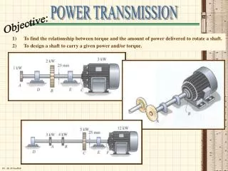
Power • Work and power in rotary motion are governed by the same equations applicable to linear displacement. • Work done in a rotary motion is the product of the force multiplied by the distance through which it moves, which in one revolution is equal to the circumference.
Power • Horsepower = 33000 lb-ft/min • HP = Force x 2 x 3.14 x radius x rpm 33000 = Torque (lb-ft) x rpm or 5250 = Torque (lb-in) x rpm 63025
Power • Providing both torque and speed are available the absorbed power can be calculated as follows: • Power (hp) = Torque (lb-in) x Speed (rpm) or 63025 Torque (lb-in) = Power (hp) x 63025 Speed (rpm)
Gearset Ratio • Gear systems are normally used to reduce the speed of rotation. The amount that the speed is reduced is referred to as the ratio. • Example: Ratio = Input Speed Output Speed
Gearset Ratio • With gear systems the amount of speed reduction depends on the number of teeth on each of the gears. • Ratio = Input Speed = Output Gear Teeth Output Speed Input Gear teeth Example: Ratio = 1500 rpm = 30 Teeth = 5 : 1 300 rpm 6 Teeth
Torque • Torque is a force applied at a distance resulting in a rotary motion. • Torque is measured in units of force multiplied by distance. Force Distance Torque = Force x Distance
Calculation No. 1 Torque = Force x Distance Torque = 100 lb x 20 in = 2000 lb-in Nm x 8.85 = lb-in N x 0.2248 = lb m x 3.281 = ft Torque (inch) 40 in. 100 lb
Torque Demonstration 2 in 1750 rpm Weight = 36 lb Shaft Diameter = 2 in Torque = Force x Radius = 36 lb x 1 inch = 36 lb-in 3 lb-ft 36 lb
Horsepower Demonstration • Horsepower Calculation : hp = Force x 2 x 3.14 x radius x rpm 33000 hp = 36 lb x 2 x 3.14 x 1 in x 1750 rpm 33000 x 12 in/ft hp = 1 hp
Input Torque Demonstration • Input Torque Calculation: Cone Drive Model HO15-2, 30:1 ratio Hand Operation = 30 rpm Input Torque = 36 lb-in = 2 lb-in 30 x .60
Friction • Friction is the resistance to motion produced when one body is moved over the surface of another body. • The magnitude of friction is a function of the following factors: 1. The forces pressing the two surfaces together. 2. The smoothness of both surfaces. 3. The materials of the two surfaces. 4. The condition (wet or dry) of the two surfaces.
Friction • There are three types of friction: 1. Static friction is the high friction that exists before movement takes place. 2. Kinetic or sliding friction is the constant friction force developed after motion begins. 3. Rolling friction is the constant friction force developed when one hard, spherical or cylindrical body rolls over a flat hard surface. Rollingfriction forces are less than sliding friction.
Bill Johnson: Gearbox Efficiency • The efficiency of a gear system measures how much power is lost. • All gear systems waste some power because of frictional forces acting between the components. In addition to the gearset mesh losses there are fixed losses due to oil seal drag, bearing friction and the churning of the oil.
Gearbox Efficiency • The efficiency is the ratio of the output power to the input power expressed as a percentage. • The amount of loading affects efficiency. A gearbox loaded at rated capacity is more efficient than at light loads due to the fixed losses which are relatively constant and proportionally higher at light loads.
Gearbox Efficiency • Efficiency = Output Power (hp) x 100 Input Power (hp) or O. T.(lb-in) x Output Speed(rpm) x 100 63025 x Input power (hp)
Gearbox Efficiency • With most types of gearing the efficiency does not change significantly with speed, ratio or driven direction. However, with worm gearing efficiency does change with speed, ratio and driven direction. If a worm gearbox is required to start under load consideration must be given to starting efficiency which can be considerably less than the running efficiency.
Worm Gear Backdriving • Worm ratios up to 15:1 (12° or higher helix) can be backdriven and will overhaul quite freely. • Worm ratios from 20:1 to 40:1 (12- 4 1/2° helix) can be considered as overhauling with difficulty, especially from rest. • Worm ratios 40:1 and higher (3° or less helix) may or may not backdrive depending on loading, lubrication and amount of vibration. Worm gears can not be relied on to prevent movement in a drive train. Whenever a load must be stopped or held in place a brake must be incorporated to prevent rotation of the gearset.
Worm Gear Stairstepping • Self-locking worm gear ratios (40:1 & higher) are susceptible to a phenomenon called “stairstepping” when backdriving or overhauling. If the worm speed is less than the lockup speed of the gearset and the inertia of the worm is not comparable to the inertia of the overhauling load an erratic rotation of the gearset may occur. At the point of irreversibility the worm may advance ahead of the gear through the gearset backlash and then the descending load causes the gear to catch up to the worm and engage it with an impact.
Calculation No. 1 rpm = Linear Speed Drum Circ. 6 ft/sec x 60 = 360 ft/min rpm = 360 ft/min 2 x 3.14 x 4.5 ft = 12.74 rpm Linear Speed (ft/min) to RPM 6 ft/sec. 9 ft
Gearset Backlash • Gearset backlash is defined as the rotational gear movement at a specified radius with the gears on correct centers and the pinion prevented from rotating. This value is generally converted to arc minutes or degrees. • Backlash is important whenever indexing, positioning or accurate starting and stopping are required.
Gearbox Backlash • When a gearset is assembled into a gearbox the resulting rotational movement will be affected by the following: 1. Gearset backlash 2. Worm and gear bearing endplay 3. Housing center distance 4. Worm and gear bearing fits 5. Worm and gear bearing runout 6. Worm, gear and gearshaft runout 7. Temperature
Overhung Load • An overhung load is an external force imposed on the input or output shaft of a gearbox. The force can be due to transmitted torque from belts, chains, gears or suspended loads as with a hoist or lift application. • Gearbox OHL capacities are limited by shaft, case or bearing capacities.
OHL(lb) = 126000 x hp x FC PD x rpm FC = Load Factor Sprocket 1.0 Gear 1.25 V-Belt 1.5 Flat Belt 2 to 3 OHL = 126000 x 2 x 1.25 5 x 100 = 630 lb Overhung Load Gearbox 2 hp at 100 rpm 5” gear PD
Bending Moment • A bending moment is a turning moment produced by a distant load usually applied to the output shaft of a gearbox, typically found with vertical stirrer/agitator reducers with unsupported paddle shafts. • The bending moment is the product of load and distance from the gearbox.
Moment of Inertia • A moving body has stored kinetic energy proportional to the product of its mass and the square of its velocity. • When a large mass is accelerated to a high velocity in a short time the power required will be greater than that needed to maintain that velocity. • Changing the mass has less effect than changing the velocity.
Moment of InertiaTorque Calculation • Torque to accelerate a rotating body is the product of the moment of inertia and the angular acceleration. Weight (lb) Torque (lb-ft) Moment of Inertia (lb-ft-sec2) Speed (rpm) Angular Acceleration (rad/sec/sec) Radius of Gyration (ft) Time (sec)