Download

1 / 88
2.48k likes | 5.84k Vues
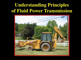
TRANSMISSION OF POWER. What is a transmission system?. The rotational motion can be transmitted from one mechanical element to the other with the help of certain systems known as transmission system (Drive). The methods of power transmission are (Types of drives) . Belt drive Chain drive.

E N D
TRANSMISSION OF POWER Dept. of Mech & Mfg. Engg.
What is a transmission system? The rotational motion can be transmitted from one mechanical element to the other with the help of certain systems known as transmission system (Drive). Dept. of Mech & Mfg. Engg.
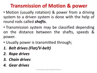
The methods of power transmission are (Types of drives) • Belt drive • Chain drive. • Gear drive. • Rope drive. Dept. of Mech & Mfg. Engg.
Open belt drive It is employed when the two parallel shafts have to rotate in the same direction. Dept. of Mech & Mfg. Engg.
Open belt drive Dept. of Mech & Mfg. Engg.
Open belt drives • When the shafts are placed far apart, the lower side of the belt should be the tight side and the upper side must be the slack side. • When the upper side becomes the slack side, it will sag due to its own weight and thus increases the arc of contact. Dept. of Mech & Mfg. Engg.
Open belt drive Dept. of Mech & Mfg. Engg.
Flat belt drives of the open system should always have: • Their shaft axes either horizontal or inclined. • They should never be vertical Dept. of Mech & Mfg. Engg.
CROSSED BELT DRIVE It is employed when: • Two parallel shafts have to rotate in the opposite direction. • At the junction where the belt crosses, it rubs against itself and wears off. • To avoid excessive wear, the shafts must be placed at a maximum distance from each other • Operated at very low speeds. Dept. of Mech & Mfg. Engg.
Crossed belt drive Dept. of Mech & Mfg. Engg.
Pulley Pulleys are used to transmit power from one shaft to the other at a moderate distance away by means of a belt or strap running over them. Dept. of Mech & Mfg. Engg.
What is crowning in a pulley? When the flat belt on cylindrical pulley is off-center and the pulley rotating the belt quickly moves up to the largest radius at the top of the crown and stays there.The crown is important to keep the belt "tracking" stable, preventing the belt from "walking off" the edge of the pulley. A crowned pulley eliminates the need for pulley flanges and belt guide rollers. Dept. of Mech & Mfg. Engg.
About Crowning • When a flat belt runs over two pulleys, only one of them needs to be crowned to achieve lateral stability. • The amount of curvature required in actual machinery is small. • The method works for belts of leather or rubberized fabric that have some elasticity. Dept. of Mech & Mfg. Engg.
Benefits of Crowning of a pulley • Crowning of pulleys provides an automatic correction to mis-tracking caused by transient forces that are applied to the belt. • Without crowning these transient forces cause the belt to be displaced without consistent means of returning to its normal path. • This can cause belt edge cupping and wear. For this reason it is wise to select a conveyor with pulley crowning. Dept. of Mech & Mfg. Engg.
Pulley crowning Critical dimensions: Crowning of pulleys should not exceed 25mm on the dia. / mtr of width Width of the pulley should be 1/4th greater than width of the belt Min. dia. of the belt should be at least 25 times thickness of the belt used to run the pulley Dept. of Mech & Mfg. Engg.
Types of pulleys • Stepped cone pulley (Speed cone) • Fast and loose pulleys • Guide pulley (Right angled drive) • Jockey pulley • Grooved pulley • Wrought-iron pulley Dept. of Mech & Mfg. Engg.
Stepped cone pulley • When speed of the driven shaft is to be changed very frequently • Used in lathe, drilling m/c etc.. • Integral casting • One set of stepped cone pulley mounted in reverse on the driven shaft Dept. of Mech & Mfg. Engg. Link
Stepped cone pulley f Dept. of Mech & Mfg. Engg.
Fast and Loose pulley • When many machines obtain the drive from a main driving shaft, • Run some machines intermittently without having to Start and stop the main driving shaft • Fast pulley • Securely keyed to the machine shaft • Loose pulley (with brass brush) • Mounted freely on the machine shaft • Rotates freely Dept. of Mech & Mfg. Engg.
Fast and Loose pulley Dept. of Mech & Mfg. Engg.
Working When the belt is on the fast pulley, • Power transmitted to the machine shaft When machine shaft is to be brought to rest, • Belt is shifted from fast pulley to loose pulley Note: • Axial movement of the loose pulley towards fast pulley is prevented • Axial movement of the loose pulley away fast pulley is prevented Dept. of Mech & Mfg. Engg.
Jockey Pulley If • Center distance is small • One pulley is very small • Arc of contact small Then • Use idler pulley • Placed on the slack side of the belt Result • Increase in arc of contact • Increase in tension • Increase in power transmission Dept. of Mech & Mfg. Engg.
k Jockey Pulley f Dept. of Mech & Mfg. Engg.
Guide pulley (Right angled drive) Use: • To connect non-parallel shafts those which intersect and those which do not intersect to guide the belt in to the proper plane • When two shafts to be connected are close together Dept. of Mech & Mfg. Engg.
Guide pulley (Right angled drive) Guide Pulley Dept. of Mech & Mfg. Engg.
Grooved Pulley The effect of groove is to increase the frictional grip of the rope on the pulley. This reduces tendency to slip. The groves are V-shaped. Angle between 2 faces: 400 – 600 Uses: • Used in V-belts, rope. • Transmission of large powers over great distances Dept. of Mech & Mfg. Engg.
Wrought-iron pulley • Light, strong and durable • Entirely free from initial strains • To facilitate the errection of pulleys on the main shaft, • they are usually made in halves and parts are securely • bolted together. Dept. of Mech & Mfg. Engg.
(r1 -r2)2 (r1+ r2) + L = + 2 h Length of a belt Open belt drive: Dept. of Mech & Mfg. Engg.
Crossed belt drive: (r1 + r2)2 e (r1+ r2) + L = Length of a belt
Effect ofsum of pulley diameter on the length of belt for open type • Any variation in which (r1+ r2) is kept constant will vary the length of the belt because of the term containing r1- r2 • If speed cones are connected by an open belt, the belt will be slacker in some position than in others Dept. of Mech & Mfg. Engg.
Effect ofsum of pulley diameter on the length of belt for crossed type • Here r1 and r2 only occur in the form of sum, • If sum is kept constant by varying r1 and r2, length of the belt will be constant In speed cones: They are connected by crossed belt, hence • Length of belt remains constant • Sum of diameters of the corresponding steps should be constant. Dept. of Mech & Mfg. Engg.
r2-r1 d2-d1 Cos = = 2 D 2D Equation for arc of contact (angle of lap) for open belt drive (theta) Dia. of the larger pulley - Dia. of the smaller pulley = Centre distance between the two pulleys Dept. of Mech & Mfg. Engg.
r2 + r1 d2 + d1 - = Cos = 2 D 2D Equation for arc of contact (angle of lap) for crossed belt drive (theta) Dia. of the larger pulley + Dia. of the smaller pulley = 2 Centre distance between the two pulleys Dept. of Mech & Mfg. Engg.
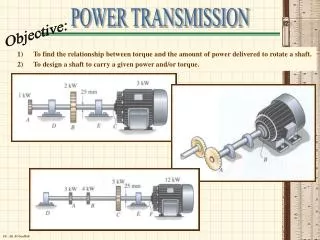
Define Velocity Ratio of Belt Drive. (Speed Ratio) The velocity ratio of a belt drive is defined as the ratio of the speed of the driven pulley to the speed of the driving pulley. Dept. of Mech & Mfg. Engg.
Obtain the expressionforvelocity ratio of belt drive. Let d1= Diameter of the driving pulley (mm) d2= Diameter of the driven pulley (mm) N1= Speed of the driving pulley (Revolutions/min OR RPM) N2= Speed of the driven pulley (Revolutions/min or RPM) If there is no relative slip between the pulleys and the portions of the belt which are in contact with them The speed at every point on the belt will be same Dept. of Mech & Mfg. Engg.
The circumferential speeds of the driving and driven pulleys and the linear speed of the belt are equal. = = = Πd1N1 = Πd2N2 = d1N1 = d2N2 Velocity Ratio = N2 / N1 = d1/d2 Velocity Ratio = = Dept. of Mech & Mfg. Engg.
Initial tension in belt drive Definition It is a uniform tension that exists initially when the drive is not in motion. It is designated as To. Formula: To = T1 + T2 2 Dept. of Mech & Mfg. Engg.
The polygon of forces acting on the element is represented by the closed quadrilateral as shown in figure. Dept. of Mech & Mfg. Engg.
Derive the expression for the ratio of tensions in belt drive. The driving pulley drives the driven pulley only if one side of the belt has higher tension than the other side The figure shows a driving pulley rotating in clockwise direction Consider a small element AB of belt, T1= Higher tension, T2= Lower tension, δθ = angle subtended by the element of AB T =tension on the slack side of the belt. μ = coefficient of friction between the belt surface and pulley rim Dept. of Mech & Mfg. Engg.
Let the tension in the tight side of the belt element AB be greater than the slack side by δT. Therefore the tension in the tight side of the belt element is T +δT. If R is the normal reaction exerted by the pulley on the element of the belt. Then, The force of friction μR acts perpendicular to the normal reaction R in the direction opposite to the direction of motion as shown in figure. Dept. of Mech & Mfg. Engg.
Element AB will be in equilibrium only when following forces act on it • Tension T on the slack side at A • Tension T +δT on the slack side at A • Normal reaction R • Frictional force μR acting perpendicular to R Dept. of Mech & Mfg. Engg.
+ R = Resolving all the forces in the direction of R. = + For small angles the following assumptions can be made. Sin δθ/2 = δθ/2 & δT. δθ /2 is neglected. R= 2T R =T δθ ------------------------------ (1) Dept. of Mech & Mfg. Engg.
μR = - Resolving all the forces perpendicular to R = + - = For small angles Cos δθ/2 = 1 μR = δT ---------------------- (2) Substituting equation (1) in (2) μT δθ = δT Dept. of Mech & Mfg. Engg.
= e μ θ μT δθ = δT Substituting equation (1) in (2) = μ δθ Integrating δθ between 0 and θ and tension δT between T2 and T1 log e = μθ Dept. of Mech & Mfg. Engg.
Slip What is slip? • The sliding motion of the belt which causes a relative motionbetween the pulleyand the belt. The equation is, δT= μR Dept. of Mech & Mfg. Engg.
Creep in Flat belt drive • The phenomena of alternate stretching and contraction of the belt results in a relative motion between the belt and the pulley surface. • This relative motion is called creep. Dept. of Mech & Mfg. Engg.
Creep in Flat belt drive This results in: • Loss of power • Decrease in the velocity ratio Dept. of Mech & Mfg. Engg.
v (T1-T2) P = * HP 4500 v= d N in m/min T1, T2in kgf Power transmitted in a belt drive Dept. of Mech & Mfg. Engg.
(T1-T2) * v P = kW 60,000 v= d N in m/min T1, T2 in Newton Power transmitted in a belt drive Dept. of Mech & Mfg. Engg.
What are the different types of gears used in gear drives? Explain. The different types of gears used are: 1. Spur Gears - For Parallel Axes shafts. 2. Helical Gears - For both Parallel and Non-parallel and non-intersecting axes shafts. 3. Spiral Gears - For Non-parallel and Non-intersecting axes shafts. 4. Bevel Gears - For Intersecting Axes shafts. 5. Worm Gears - For Non-Parallel and Non-co-planar axes shafts. 6. Rack and Pinion - For converting Rotary motion into linear motion. Dept. of Mech & Mfg. Engg.